\We are approaching completion of the assembly of this car begun perhaps 10-15 years ago. The owner, Andy Leavitt, a NASA engineer passed away 7 years ago and the car sat in the garage. Andy’s wife wants to be driving it as she once did in SoCal. Today I was able to ring out the lights I now have tail lights and probably brake lights when the new brake switch arrives. On the front end I have high and low beams and sidelights-but no turn signals. The car has a Lucas Hazard light box with a flasher unit, a 6 pole switch which has been modified, a pile light which is non-op and twi disconnected wires, I have tried to find a correct writing diagram but there is none in my Bentley, Any suggestions? Thanks to all!
Mike Moore
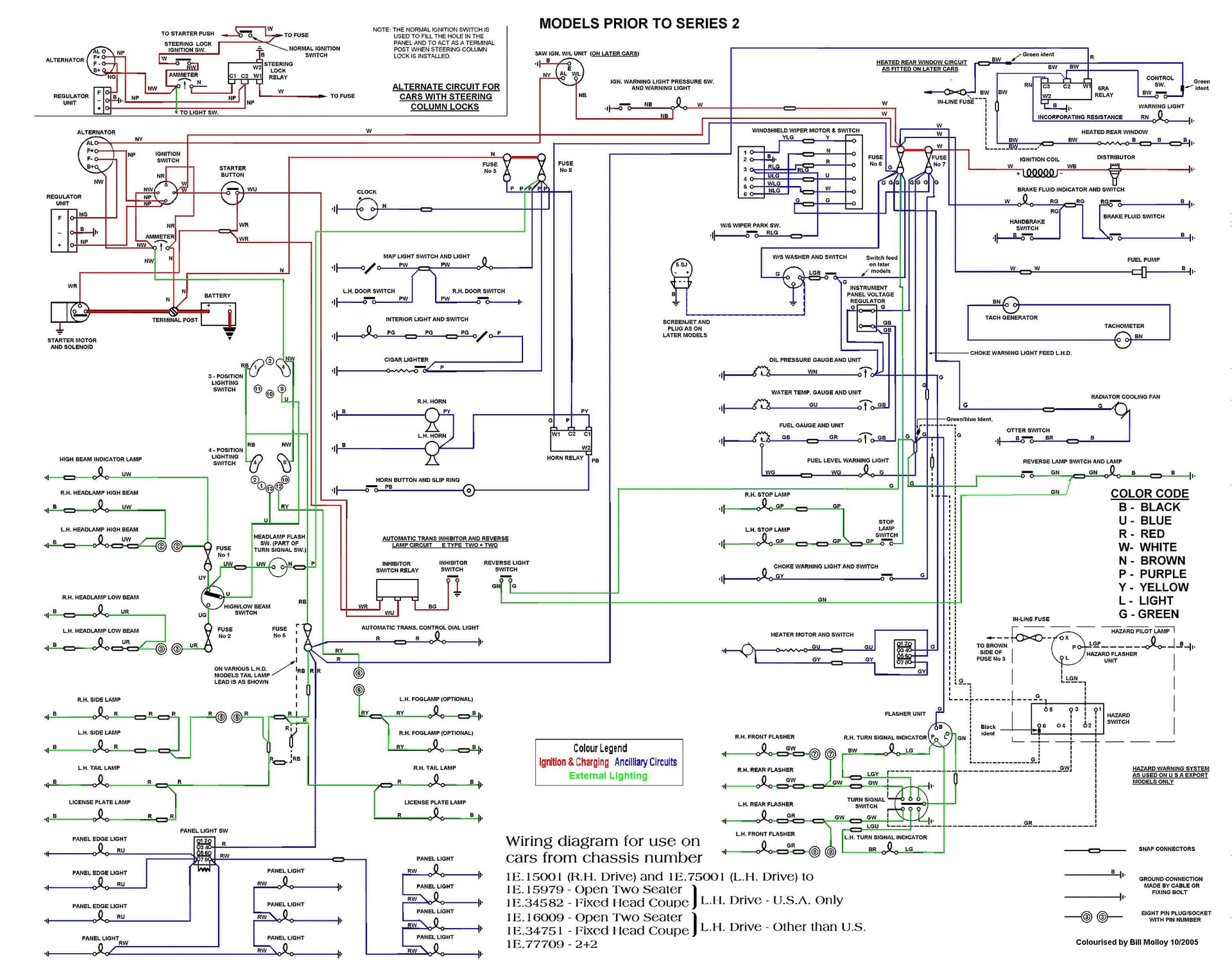
Michael, This diagram shows the hazard switch wiring. ** I edited this to show the corrections descussed below so that this document will not create confusion in the future. jc
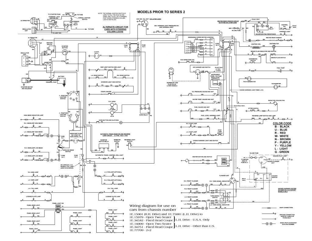
Michael, This diagram shows the hazard switch wiring.
Thanks John , I am sure it is here somewhere, I just need ti sound some time with it
Best, Mike
Michael.
Hazard switch wiring is in lower right corner of the diagram.
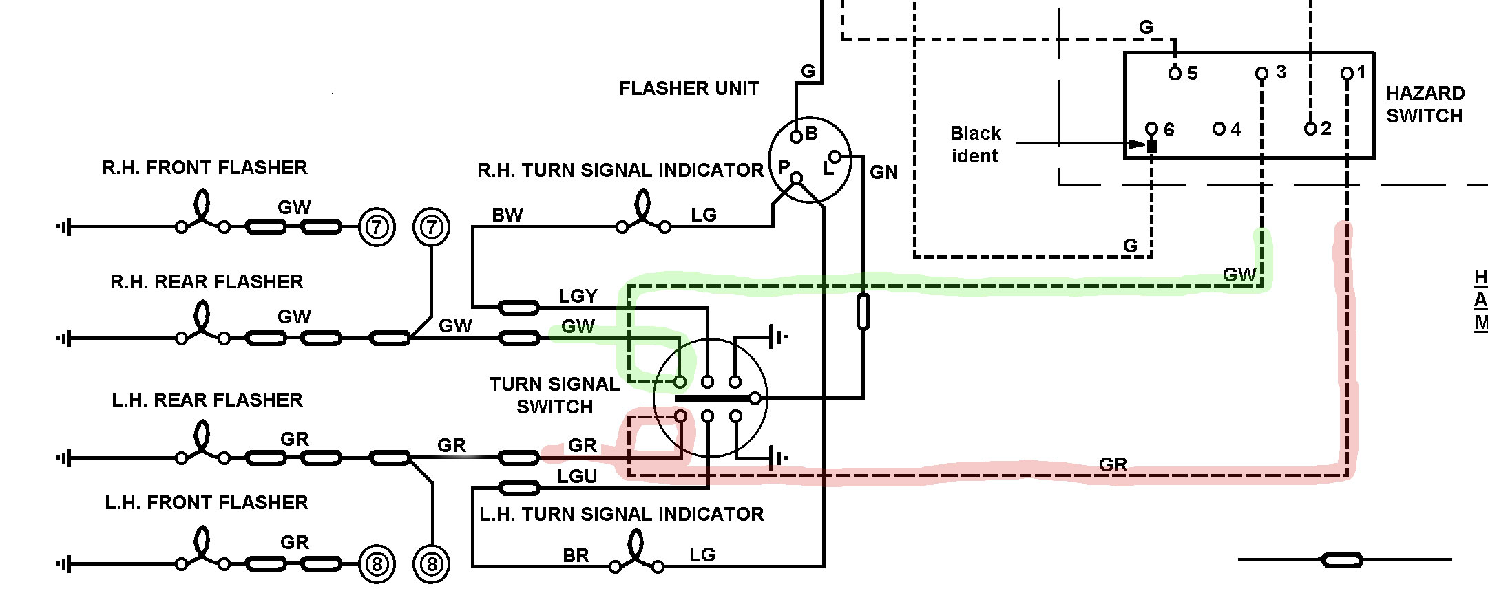
Took a close look and that wiring diagram is a version showing a GR from hazard switch terminal 1 directly connected to a GW from hazard switch terminal 3, which arrangement will likely result in failure to proceed. The wires need to connect to separate terminals on the turn signal switch as per this version from the E-Type UK forum:
No idea where these anomalies come from as the diagrams are otherwise the same.
No idea where these anomalies come from as the diagrams are otherwise the same.
Bob, thanks for the tips! I made a copy of the diagram from John and just visited the car to confirm some wiring. There was a vey nice condition 67 (?) hazard light assy which had plenty of pictures of the wiring. Initially, it looks to be wired identically to the 67 in the car I am working on. I went over to see the car and the owner said when she got up this morning the right side flashers, front and rear were flashing . They stopped when she turned off the hazard lights. I was getting flashing voltage out of the GW wire coming from the hazard switch, Right side was flashing, but not the left. The left GR wires were flashing voltage, I then found a bare bullet plastic jacket (Other wires are fabric jacketed and we think the owner bought a hazard flashier jacket)GR wire hanging down in the flasher area and it had flashing 12v on it. I need to find out where it connects to the body harness. Your new diagram will be helpful, Thanks, Mike Moore Morgan Hill, Ca,
Actually that schematic came from this forum, I drew them about 20 years ago, along with an 3.8L one and also a S3 one. Richard Ligget drew one for the S2 so I didn’t bother. The S3 one is quite complex as it includes the circuits for the seatbelt warning system which wasn’t on all cars.
pauls
1 Like
Thank you for all your trouble Paul!
Bob. then you believe these are the most correct?
Thanks
Michael Moore
If anyone finds an error I’d love to hear it, more than happy to make corrections and don’t want to mislead anyone. As said tho its 20 years old, I’ve heard nothing yet but still listening ![]()
pauls
1 Like
Paul,
The discrepancy I found is not on yours but on the version initially posted by John, and which was also posted on the E-Type forum as a colourised version provided by Bill Molloy in 2005. It had been edited to indicate some circuit colours but errant disconnections appear to have crept in. :

Wiring for the hazard switch is shown dotted as it was fitted to US export models only, but the GR and GW connections to the turn signal switch have been deleted. Doubt it was factory drawn in that manner but we may never know. Your version posted on XKE data is correct.
Michael,
Check the chassis number of the vehicle you are working on to confirm if the diagram applies but it should be correct if it is a Series 1 4.2 with the hazard warning system installed.
Bob
Thanks Bob,
I remember the colored version I didn’t examine it for errors as I thought the colors would help folks, did not assume it would have been modified. My drawing was done by hand using Corel Draw, so the shapes of some components are not perfect could be identified in the colorized version. It was originally a scanned image of the Bentley book which was imported to Corel and I simply cleaned it, added a few clarifications and saved it in digital format for folks to print at home. I always carried one in the car as well. I’m glad to know it has survived, so far, without misleading anyone ![]() The S3 diagram was a great deal more complex as the book had the diagram on one page and component descriptions on another, I combined the descriptions within the diagram so everything could be on one page and printed for use in the garage without worry of getting the book dirty.
The S3 diagram was a great deal more complex as the book had the diagram on one page and component descriptions on another, I combined the descriptions within the diagram so everything could be on one page and printed for use in the garage without worry of getting the book dirty.
pauls
I do have one question Paul, on the Hazard switch wiring, you show two G/W wires from the turn signal switch. One goes to the G/W for the right turn signal lights which seems right, but the other joins to the G/R for the left signal. Shouldn’t the left turn signal wire be G/R right from the switch?
John North
S1 Roadster
Paul, thanks for looking into it. There must be several versions of it out there - if you look closely at the OP’s version, you will see what I mean. Where can I get your version?
John North
John, Paul and Bob,
Thanks for pointing out the error in my original diagram posting. I have edited my copy of that file to show the GR and GW wires connecting to the proper lugs now so that my post will not continue to propagate that error.
Best regards,
John Carey
S1 FHC
Hi John,
I did see the error at the OP, do not know why that happened as the colorized version was most certainly my original. Did not think it would have been modified.
It has been posted on xkedata since I drew it at:
http://xkedata.com/pdf/42wiring.pdf
I have jpg and tiff image formats, I’m sure the forum won’t allow the tiff as it’s huge but very high resolution. The jpg version is still huge but I’ve reduced it down to 25% of its original size, I’ll try to upload it here, fingers crossed.
pauls

John, John, Paul and Bob , thanks so much for all the help. My vision has suddenly and hopefully temporarily degenerated to double vision so I am struggling with the diagrams.(I have an eyepatch today!) It is ironic that in trying to trace the wiring out, I found the GW wire running into the GR and was very puzzled, I went back to the car and found that when the hazard flashers were flashing, I had a flashing voltage from the GW wire and from the GR wire at pin #1. No left side lights flashing, all right side flashing.
I have a geography question: There is a wiring bundle above the left panel which rests in sort of a conduit cable tray and passing near the vehicle main flasher.Someplace in there there is a GR wire with bullet which has flashing voltage synchronous to the hazard flasher. I suspect there is a connector somewhere reachable to that but I cannot see it and would appreciate any ideas as to where that properly connects Iocation). The original owner of this car, Andy Leavitt, has apparently done an excellent job of building it from a large assortment of scrapyard parts, and I am never certain if what I am seeing agrees with factory documentation or not. Again thanks for all the help folks-and three cheers for the Queen!
John Carey mentioned another wiring diagram someone had. Now John’s car is a 63, not 67. My 63 did not have a hazard flasher. There was a hazard flasher assembly on JL classified and it looked amenable to being a simple chassis installation with 5 wires w Lucas bullets to connect. Were there installation instructions for this chassis? The one in the (my) 67 is exactly a match for the one now sold and all components are functioning so if I can connect it properly it will work, I wojld rather not disassembled all and start over! Best, Mike Moore
Michael, not sure what you’re asking… the wire from the switch goes to a connector below the steering column where it hooks to a wire going out to the left side by the flasher. At that point, the wire from the column joins one going forward to the bonnet and one back to the rear. That one is a 4-way connector.
There are several connectors under the column, an isolated five-way, a couple 4 ways and straight connectors, I forget which one carries the G/R from the switch. Hopefully your colors are good - it sometimes is not easy to tell what the colors are.
Good luck
John
That helps me. I suspect that is the end of the pigtail from the turn indicator switch. I should be able to find it.
Thanks, MIke
67 OTS S1