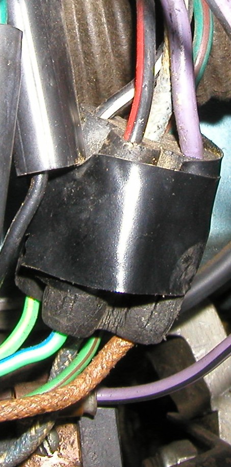
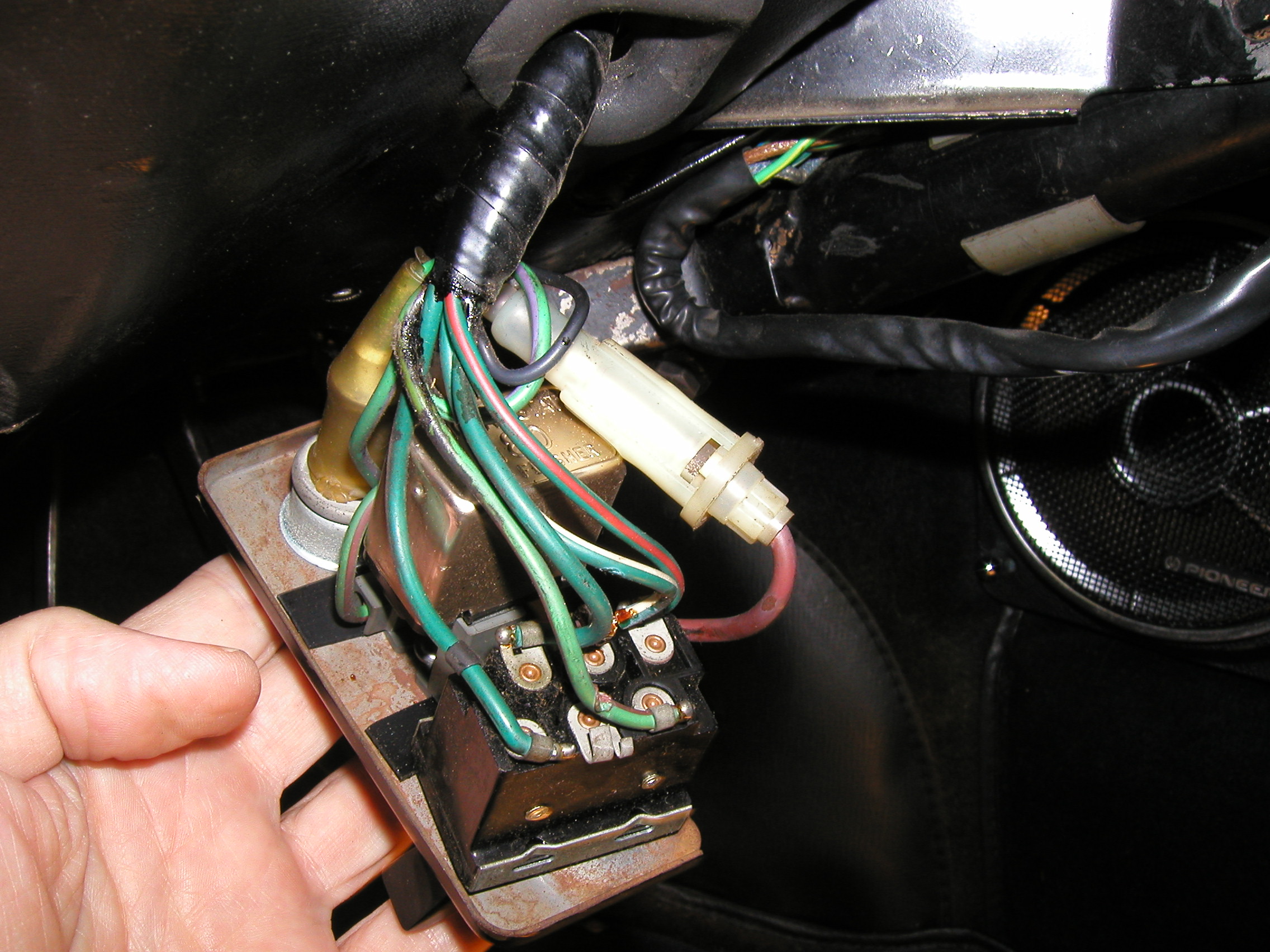
Michael, don’t know if these images will help and hope I can upload but these were the connectors to my turn signal switch, flasher and hazard switch.
pauls
Michael, don’t know if these images will help and hope I can upload but these were the connectors to my turn signal switch, flasher and hazard switch.
pauls
Paul, this will be a terrific help! Thank You. I will not be venturing over to her car until Thursday am so I have time to study and think a bit, I went over yesterday with the intention of finding the GR end of the turn signal switch and connective my GR bullet to that 4 wire connector. I was hoping that would facilitate the emergency flashers, as well as the LF and LR turn signals and side lights. (The state I had left the wiring in was as follows:
Thanks so much for the pictures!
Michael Moore
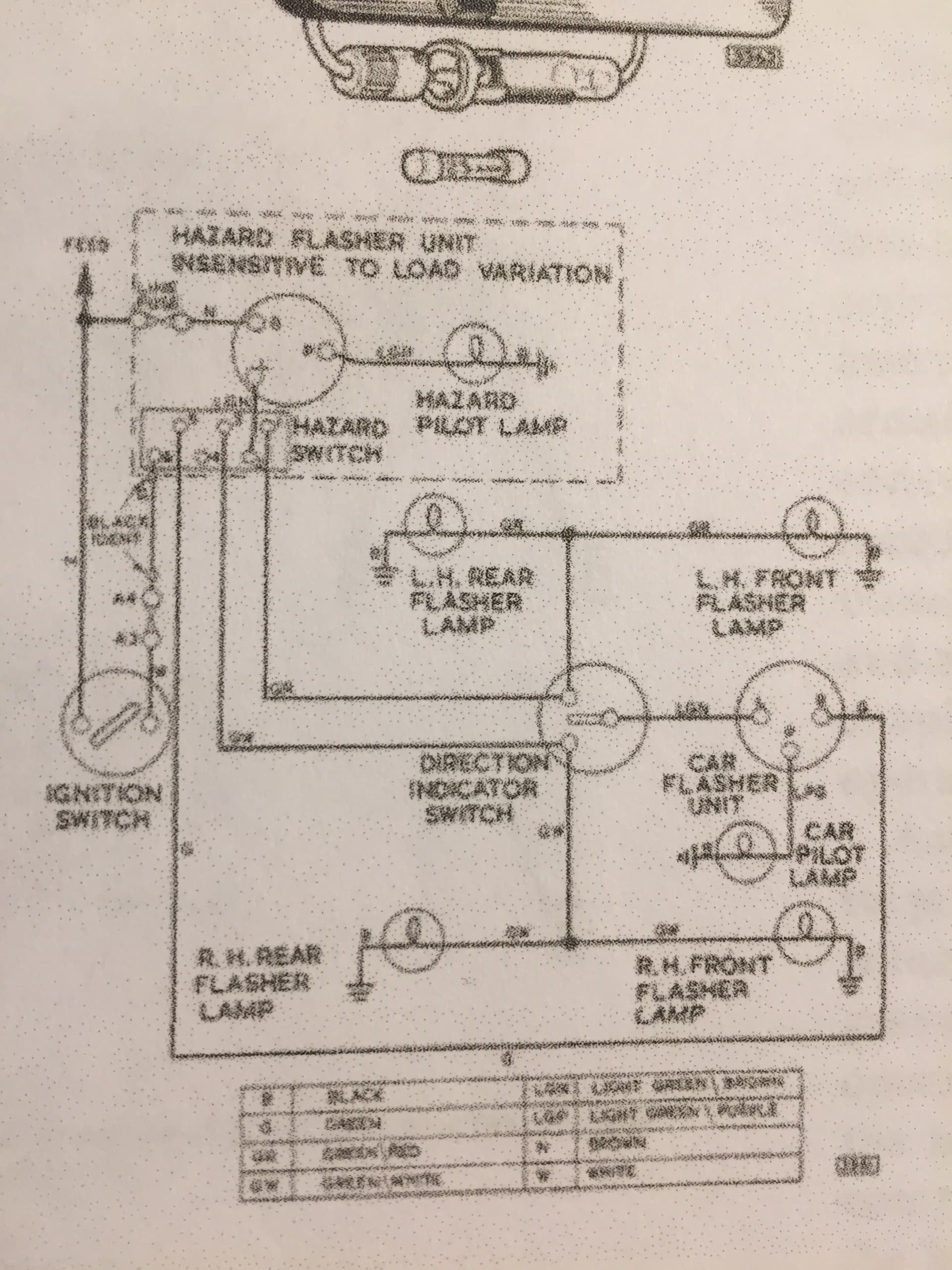
Michael, when you say terminal 1 and 5 is it the switch on the hazard unit? If so the GW wire is supposed to connect to terminal 3. That’s what the wiring diagram shows and also agrees with my hazard unit… FWIW I no longer have the car so can’t do a real time inspection but I can read the terminal number 3 in my old photos with the GW wire connected to it. Some of the wires change colors at connectors but GR should stay the same all the way from the hazard switch terminal 1 through the turn signal right to the external lamps as should the GW from terminal 3.
pauls
Sorry, my mistake. I misread my tiny note where I verified all the contacts and I did write that Terminal #3 IS the GW and Terminal #1 is GR.
Paul, I do not expect anyone to go out and got through the gymnastics to read these wires! I have studied where they are supposed to but have to figured out how exactly to do it. I am suspicious of the TS flasher (not hazard) being faulty. The green wire current has to go through there and it has never flashed. So maybe I should make sure I am getting continuity to G on the Turn signal sw to the flasher socket, Then confirm the other connections.I do not understand what I could have done wrong to un-do the hazard chassis which was working,
Mike
Paul, I am still puzzled. I had a flashing terminal #1 GR and a flashing terminal 3 GW. Had a flashing RR tail light but not left side F or R. So I decided I needed connect Terminal 1 GR to a GR wire somewhere and it was hanging bullet down from near the main flasher. So I concluded that at the end of the turn indicator switch I would find a GR wire (I did) plugged into a connector and that is where I needed to plug this hanging GR which I did. That seems to have shut down any previous progress so (1) I need to verify exactly where it was plugged into. I did not do it personally\ due to eye issues. But here’s the puzzle. The only way the GR wire could be powered on the TS switch is by the G wire feeding the TS switch. So how is that hanging GR wire getting power from the hazard switch flasher?
Like Michael, I am also trying to figure out this wiring and your comments are very helpful.
I am using an ohmmeter to test this assembly. With the switch on, from the N wire at the hazard flasher, I have continuity to the LG/N to the switch and then to the G/W and G/R, which seems right. But I don’t have continuity at the lamp.
When I put 12v on the N wire with the switch on, seems like the lamp should light, but it does not.
The G/P at the flasher unit does have continuity to the lamp so the problem is not at the lamp.
Am I correct then that there is a problem in the flasher unit? or am I missing something here?
John North
1967 S1 Roadster
I checked my bulb and it was failed. (I am about to drive over for the day and see what other damage I can do) . Mike Moore
John, continuity to the lamp doesn’t verify the circuit is good. Bulb could be open or bad ground. Pull out the flasher unit and briefly touch 12v to the LGP wire or socket P to see if the flasher lamp lights. This will test the entire lamp circuit.
pauls
The lamp lights if I apply 12v to the LGP wire, but not when I apply it to the N wire, so it does appear to be a defunct flasher unit, correct?
John North
I returned to the garage where the 67 E Type I am sorting out lives. Owner Karen determined the green wire supplying voltage to the turn signal switch was connected to the wrong fuse. I dropped the steering wheel column and mechanically disconnected the ts switch so I could probe the wires. All those wires were correct AFTER I connected a couple of Lucas connectors which had been loose behind the dash. I also traced all the wires to the ts flasher and they were correct. I ended up with everything connected properly (I think) but decided to wait until Tuesday am when I am scheduled back. At that point, I’ll look everything over, ring out the headlight switch (I am not convinced it is controlling what it claims on the face of the dial),e.g, headlights turns on sidelights instead etc, Once I have checked those out I will turn the key on and begin to seee what lights up! Thanks, Mike
Michael, for some reason your message wasn’t complete but it sounds like you were headed in the right direction by connecting GR to terminal 1, that’s the source for the left side. There must be more to the saga unless that fixed it ![]()
pauls
I will know Tuesday morning.Maybe! Thanks, Mike Moore
Hi Michael, it looks like for some reason my screen displayed your comment twice one in its entirety and once only part of it, which is what I saw before, now se the complete message. There should be three G wires, one to the TS switch and another to the Hazard switch terminal 5 and another to terminal 6. They all appear to be from the same source, F7 so I do not know why the one to terminal 6 says it has a black identification, which is a small black sleeve at the near connector. The G to terminal 5 does not indicate any identification. Do not know the internal construction of the switch and flasher so I can’t help much there. The hazard flasher gets power via a fused N wire (always hot whereas the G wires are hot when the ign. sw. is on) from F3.
pauls
Hi Paul, I have power on the N wire going to the hazard flasher.
I spent Tuesday reconnecting numerous wires behind the tach and speedo. Some had bulbs some not, some had dead bulbs. These may have nothing to do with the current problem but they add to the confusion. After consulting with Ray Livingstone, I confirmed that I have voltage coming out of the turn signal switch on GW and GR. In an attempt to remove the flasher socket screw, I broke the flasher socket. Fortunately I have that same harness space as I removed it from a 64. It is terminated and labelled correctly via wire colors. My plan is to connect that harness to the proper terminals and put a known good flasher in the socket to see if I have normal flashers all the way around.I certainly should have as every bulb in all 4 corners have been illuminated.
Thanks the advice Paul!
Mike Moore
Good luck Michael. Wish I still had my car so I could take some additional appropriate photos and tests. I did a brief search, did not find any information on the internal workings of the flasher units so we’ll still have to go on some assumptions. Ray’s the guy with boots on the ground. I’ll help where I can.
pauls
What a Foible!
Today I expected to plug in the last wires and be done.But instead I had a terrible time ending up with me removing the ts switch again etc. I discovered I had been interpreting GN as being GREEN, In fact, as everyone else knows, it is Green with a Brown tracer (stripe). I replaced the TS flasher socket and flasher. I have decided to retire to my office (at home) tomorrow and trace out each step beginning with power entering the ts switch and ending at the flashers. To eliminate confusion, I will remove the hazard switch assy and harness for now. (My new glasses to help my double vision ought to arrive and believe me that will help! Thanks for help. Mike
Hi Michael, well a discovery like that is good. Also the colors seem to have faded over the years or possibly misinterpreted when listed as light green, they are light green but not exactly what I expected. E.g. the LGY wasn’t obvious, the LG was so close to the Y it didn’t stand out when hidden in the loom. Good luck.
pauls
I have not seen an LGY wire. I’ll try harder, My newest strategy is to try, step by step to walk my way through the diagram, e.g., power gets to the ts switch in the G wire coming from Fuseholder 7.(Although this digram shows the hazard switch gets power from the ignition switch via a white wire. If I can verify that and find that 12 v going coming from the ign switch, I’ll know THAT much is right.!
Mike
Terry, thanks so much. I had about decided I could ignore the hazard warning box and focus on getting OEM ts working first,Hmmm, Thanks for the diagram! Mike Moore