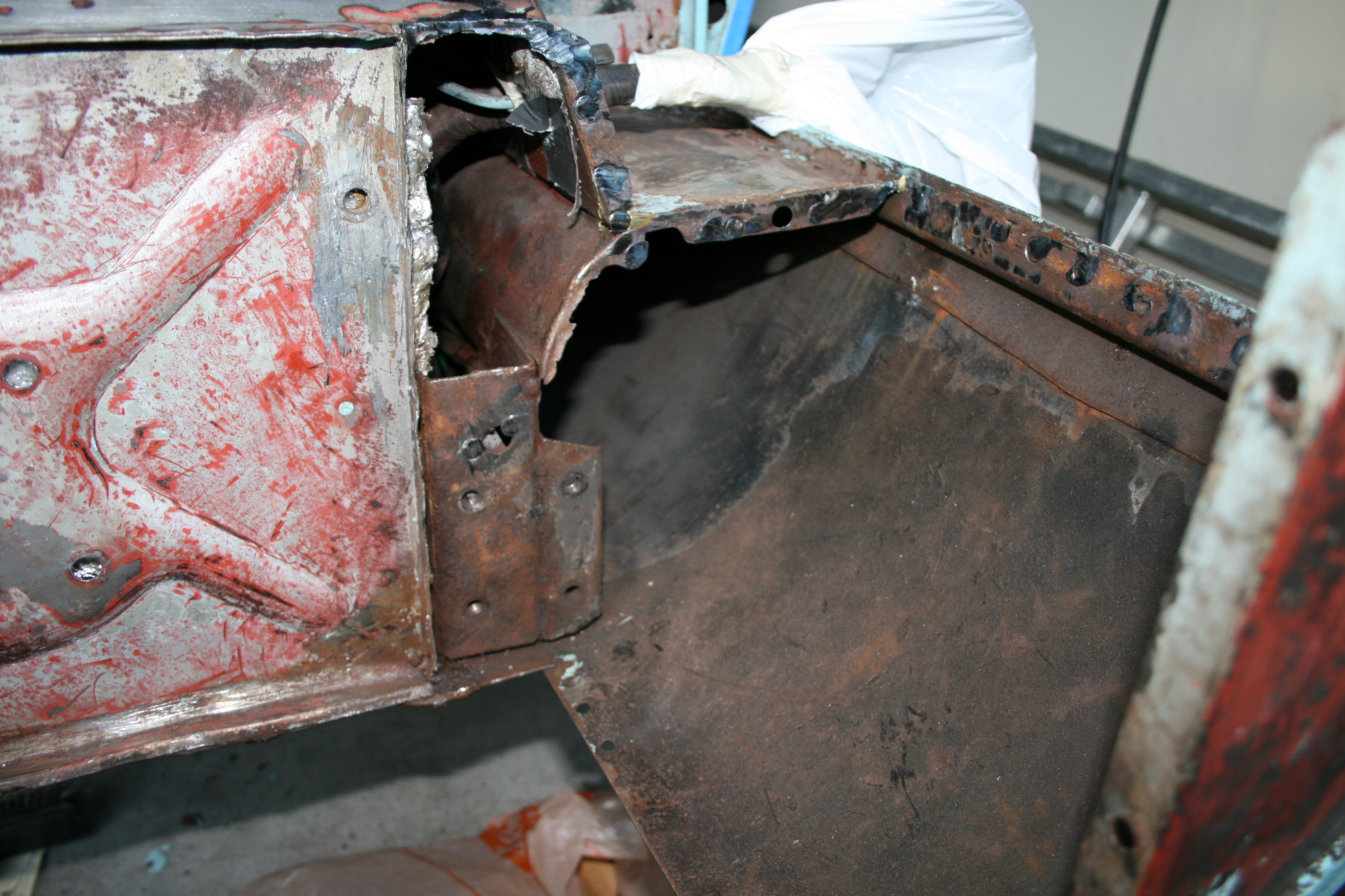
The piece you have bent at the front, the lower piece space welded at the seam and the curve on the rear is all sill. There is a rear sill closing panel that is attached to the curved part of the sill and to the inner sill. It all comes off. You can leave the rear closing panel on.
Clear as mud, huh? See Lloyd waving his arms for further detail.
I used the replacement parts I got from Chuck at Monocoque as a guide to what went where. The spot welded junction in center of your last picture requires expertise in origami to reconstruct.
Where the sill meets the side scuttle? Is that a lap joint or a butt joint? It seems like the hardest part would be the surgery to remove the old sill remnants.
The rocker panel has a lip/edge that fits under the side panel lip/edge, latching on to it, sort of like clasped hands. Easy at the factory - just install rocker, then add the side on top of it. Not so easy if the side is in place.
Removing did require surgery - amputation rather than plastic/reconstructive. Then I just spot welded, banged the whole thing in a couple of mm’s and plastered over it. LTS (Life Too short) to make it more “original”.
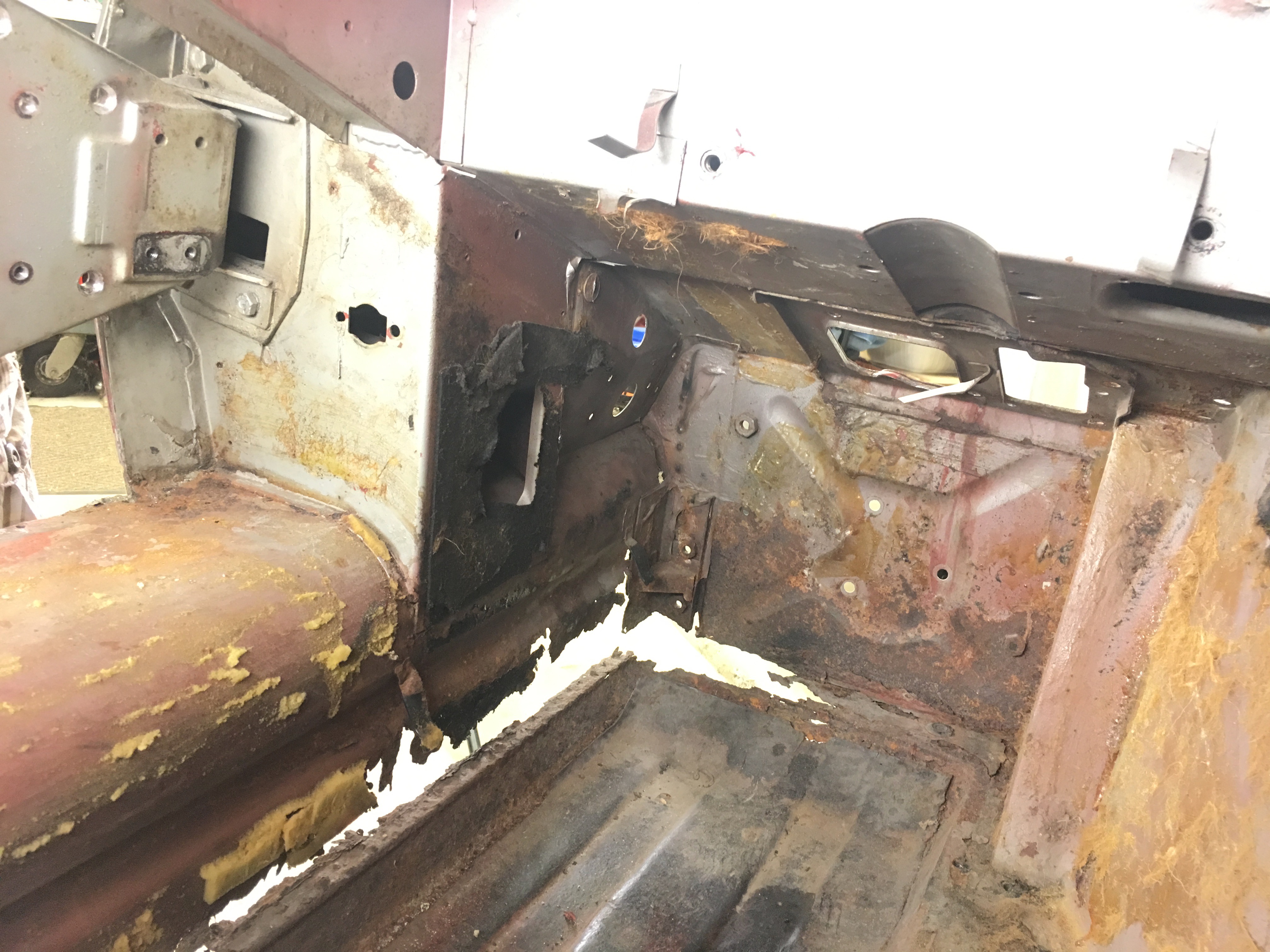
Anyone familiar with this intersection? I’m looking at the details of the inner sill and am unclear what is part of what at the corner in the photos. Is the front strut lower outer mount plate part of the inner sill, stand alone part, or what?
Does anybody have photos of “new” inner sills, full floors, mounting plate, before installation?
I have been provided the outer sill, floor footwells, and strips of metal to “repair” the inner sill from Chuck (monocoque) but looking at the floor around where the footwell goes, it’s rusted away so maybe just ordering a FULL floor would be better? Also, wondering if replacing the inner sill instead of repairing would be easier.
I am going to attempt to “repair” it and use that as a practice for learning the welding technique. But we’ll see which way I go after I see the results.
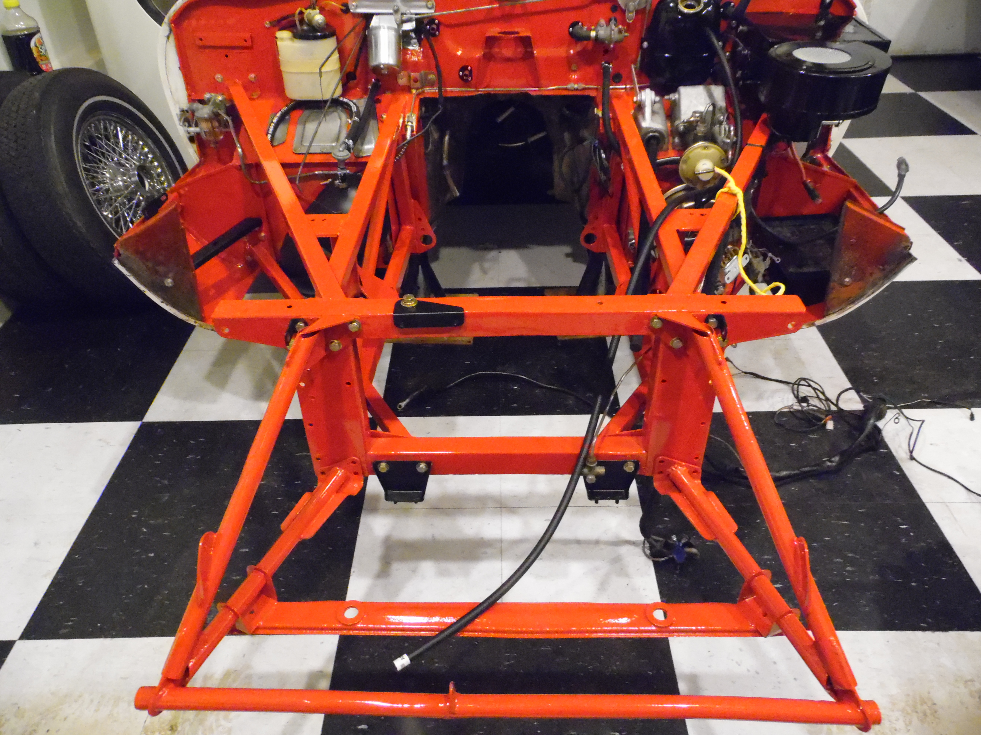
The lower subframe mounting brackets were originally part of the floor assembly which included the inner sills. The mounting bracket is actually made up of two vertical right-angle brackets with the inner sill sandwiched between them. Now you can purchase separate panels for the floor and inner sills. The diagram in the XK’s Unlimited catalog appears to show that the outer 1/2 of the mount comes attached to their replacement inner sill, whereas the inner 1/2 does not. However, it also shows that the 2 halves of the mount have to ordered together, which seems a little odd. Here’s a somewhat fuzzy photo of the area on my car after the sill closing panel was removed.
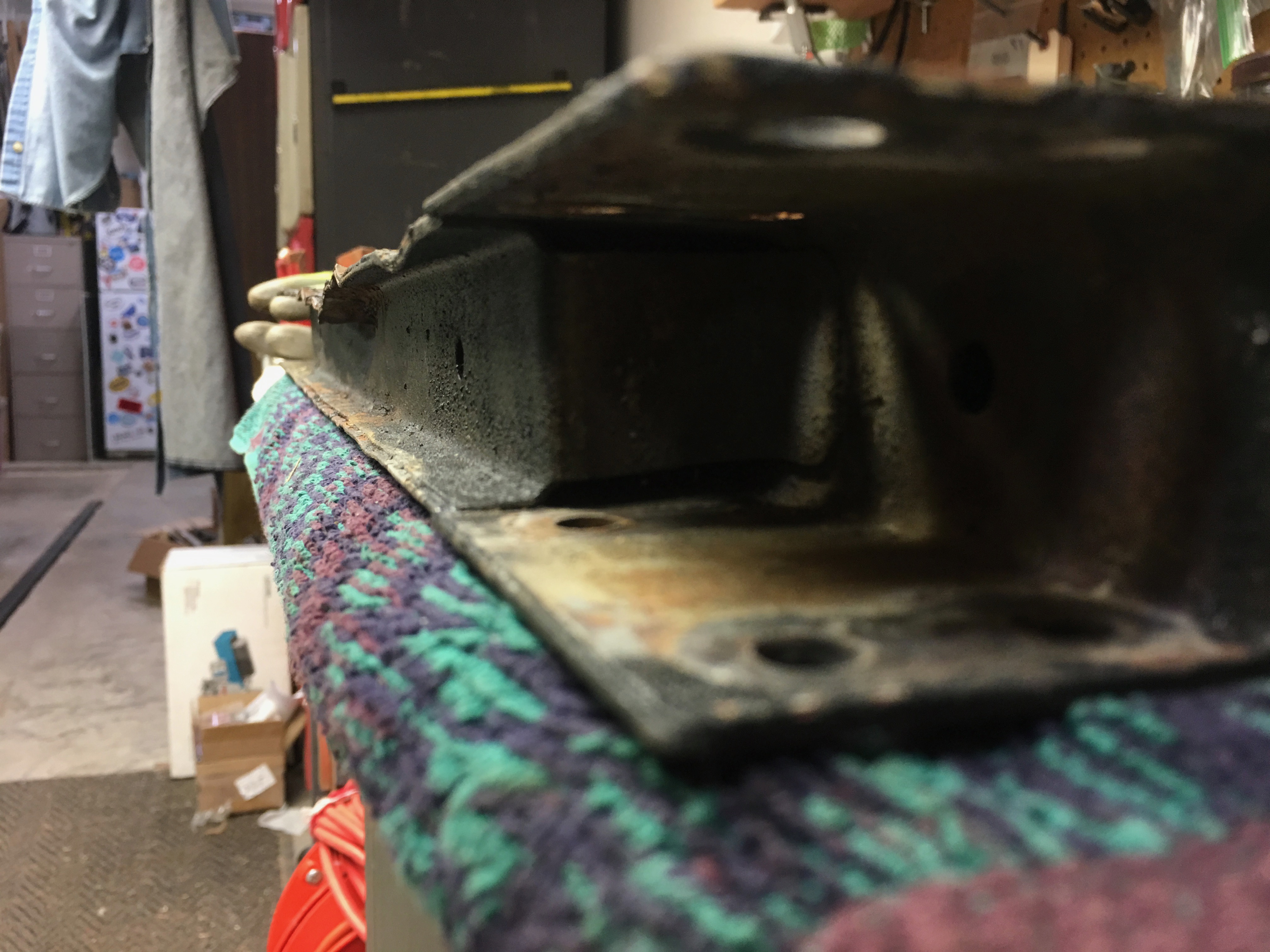
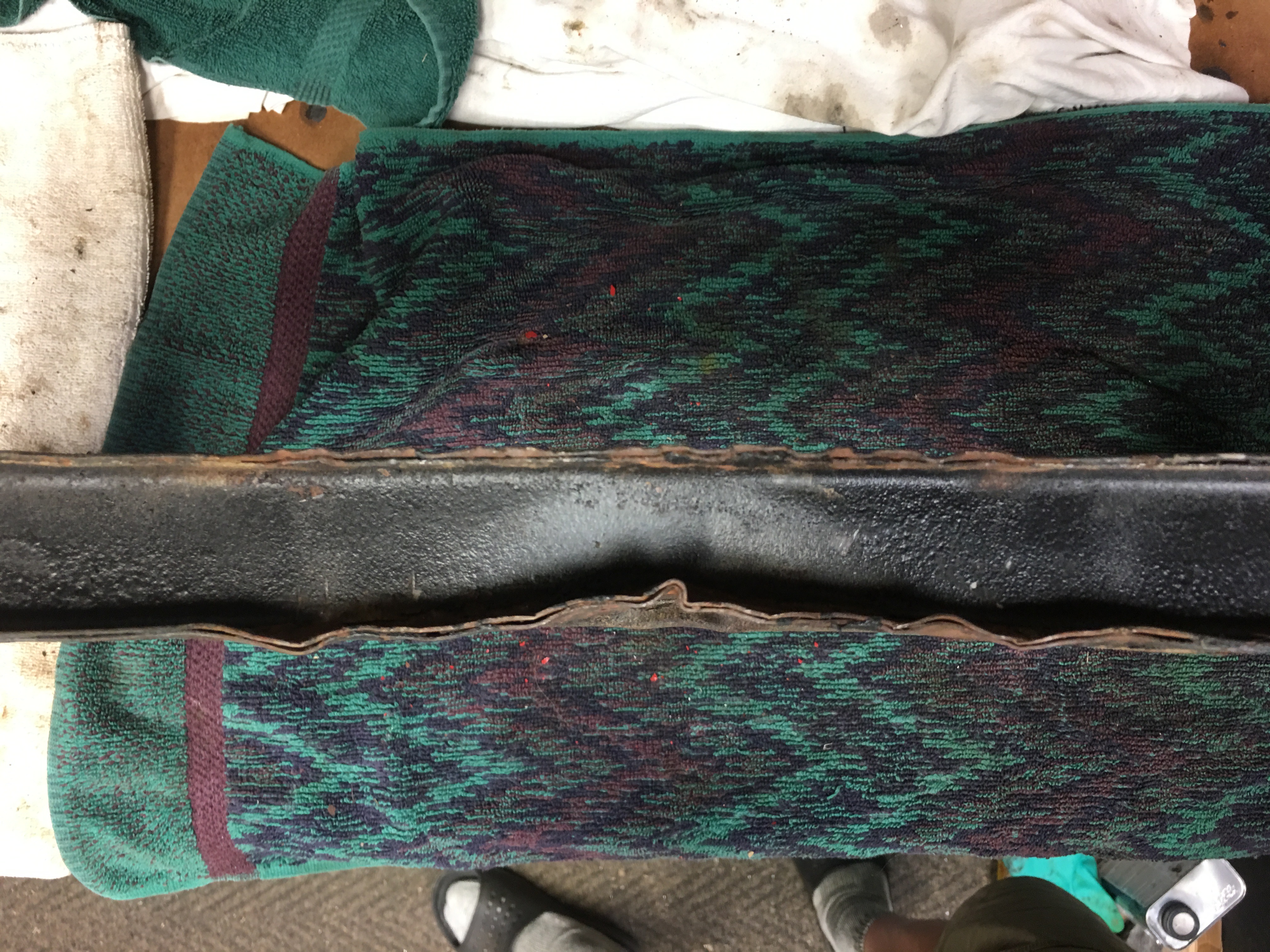
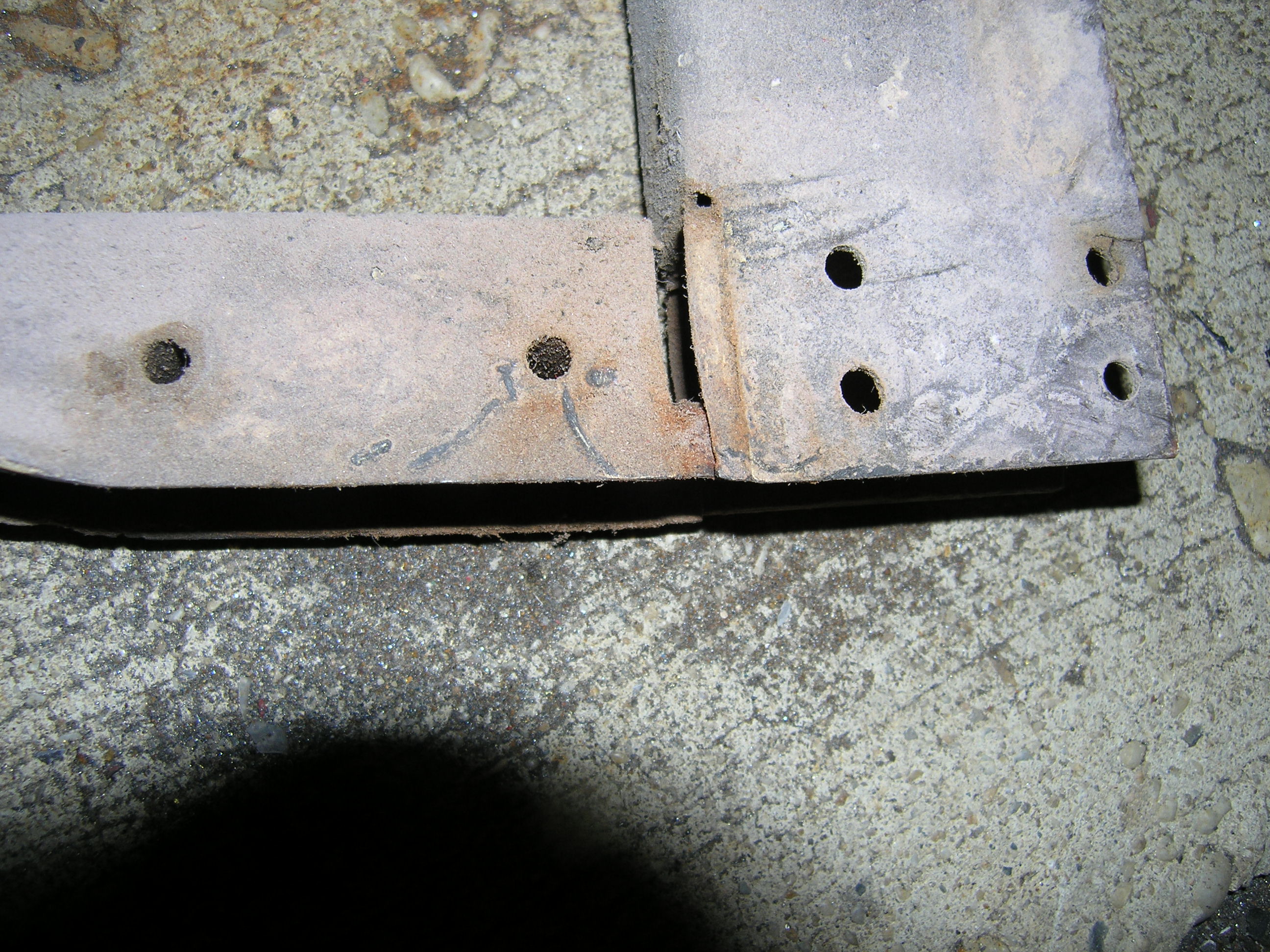
I’m trying to repair the lower section of my picture frame. I am aware I can purchase a new complete one for ~$350 but I would like to retain the original (with chassis# stamp). So far I have straightened the front flange from former jacking damage, but the rear flange and web are bent and I need advice on how to best straighten this area. I don’t believe it causes any structural issues, but it is unpleasant to the eye!
Is this part brazed or, as appears in the photo of the replacement part, just spot welded?
If just spot welded, could I not cut the part of the bottom box plate off in order to reach the top bent plate in an effort to pound it back straight, then weld the lower box plate back on? Or can I drill a hole in the lower box plate, to give me access to the top that I could use a punch to hammer thru the hole and attempt straightening the bent areas?
ANYBODY TRIED THIS BEFORE?
-Steve
The spot welds that hold the inner piece in place were broken and pushed into the outer piece. I was able to grab the edge with vice grips and pull it flush with the edge of the outer bottom member which I straightened with a hammer and a piece of I-beam for an anvil.
I spot and tack welded inner and outer pieces at the edge and then reinforced the whole thing with two pieces of angle and a flat to make a channel. You can jack up the front end under the picture frame with no fear of anything being bent.
This will give you an idea of the reinforcement. The picture was taken before I finished cleaning the part for refinishing.
Don’t worry about the ID number. Efabs will stamp your original number into the new picture frame if you can provide documents proving ownership - title?! Pictures show the condition of my picture frame after a “body shop” used it for a lifting point and a HD suspension sort of pulled it apart.
Steve. I have a new pic frame that came with my frame rail set I am not going to use and you may have it if you want. It has no numbers stamped and I have a number stamp set but they are the wrong size. I suspect most machine shops have the stamp set you would need. You could even cut the welds on the top pieces and put them together. I think a lot of work for not much gain. In any case you may have it , let me know. I love seeing your enthusiasm and how you are not afraid to tackle what can appear to be overwhelming jobs.
Cheers Jim
Great! It’s because of people like you, Paul, Erica, and many others on this website that I gain courage to battle on!!! I’ll i.m. you my address and I’m not sure how to prepay shipping but just let me know what it is and I can “venmo” it to you!
-Steve
Ok, before I admit this, there is no diagram in any of my books describing the three rubber sound dampener studs holding the fuel pump to the mounting bracket. The rear two are held on with opposing nuts/lock washers thru the bracket; easy enough. I complete removal of the fuel pump and then proceed to finish the task by removing the last dampener still attached to the bracket… after trying every tool in the box to get a grip on the nut, which is located in the “darkest depths of Mordor”, exacerbated I cracked open a beer and gave up for the evening. During sips it dawned on me… it’s a welded nut and the dampner must hand unscrews from the top!!! GOOD LORD!