Original was very brittle. Car was running okay (after some work), except it was giving me FF34 after test driving it on the interstate and then sitting at idle shortly after. I pulled the injectors and one wasn’t clicking.
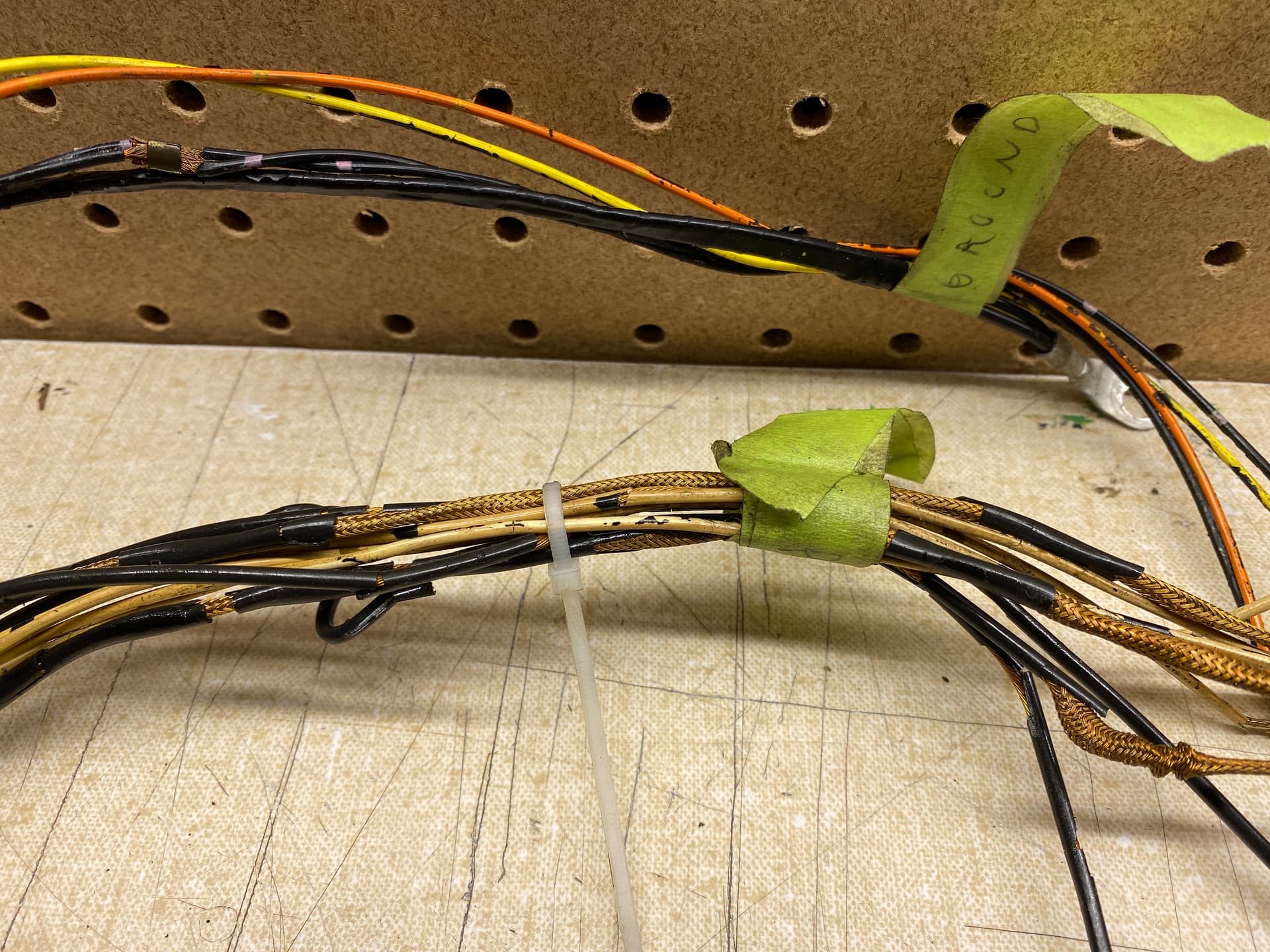
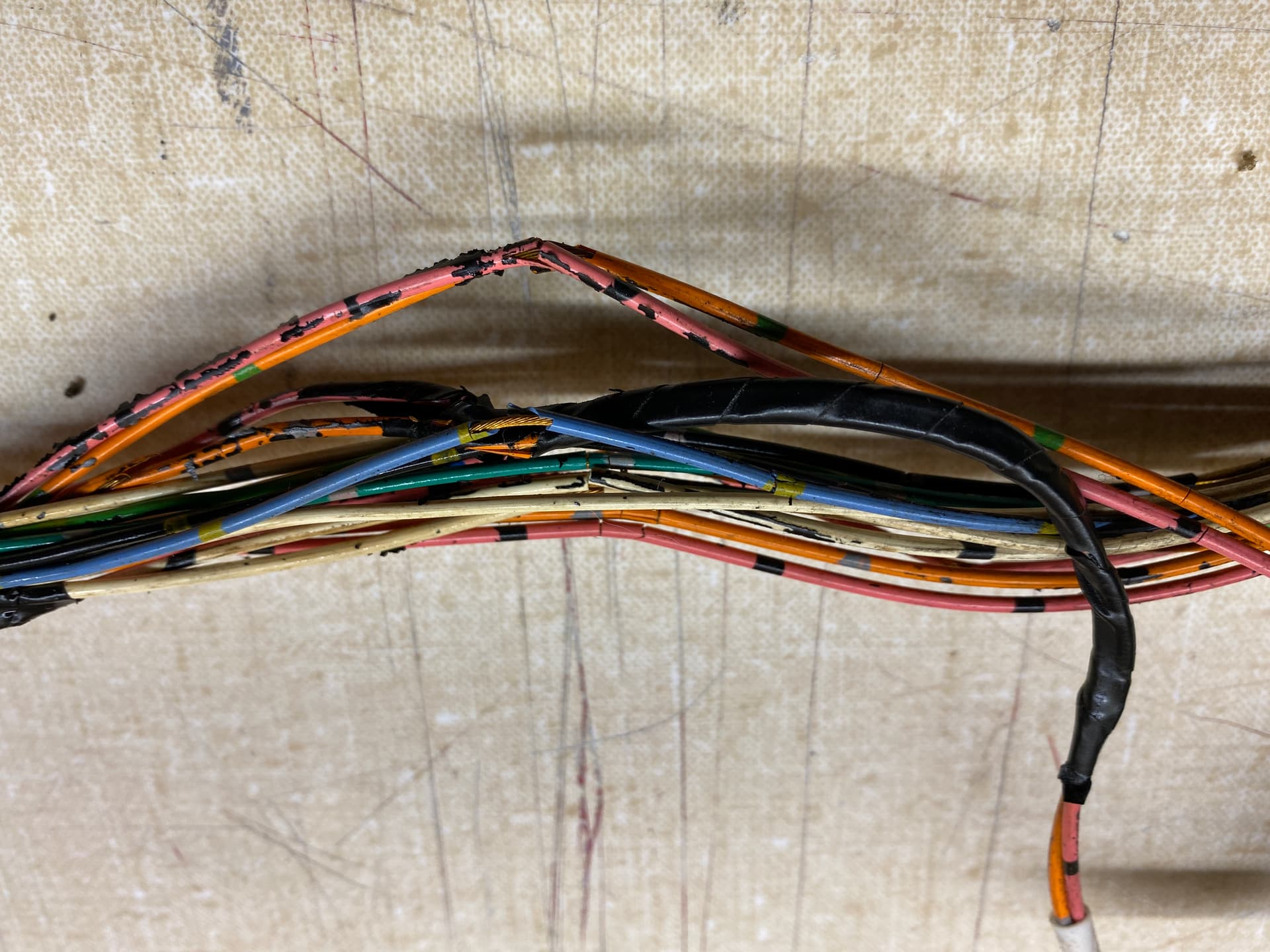
I was cleaning up the vee which led to this harness rebuild. Every time I touched the harness it would fall apart. If it was working before it certainly wouldn’t now. As you know, the injector harness is wrapped together with a lot of other wiring in the engine bay. The power module/ignition coil wiring wasn’t in any better shape.
So now the wiring harness has been pulled out, cut off near the boot that leads to the passenger footwell to the various ECUs.
It actually seems pretty straightforward once you have everything unwrapped and start separating the discrete pieces. Easiest one to separate is the Fuel injector harness (makes you seriously question why this was wrapped with the whole harness). Once you split up the 9-way connector there are a few more that can be separated - Oil pressure switch and transmitter is an easy two wire standalone section.
A couple of questions though. I’ve searched around on the forum but didn’t come up with anything.
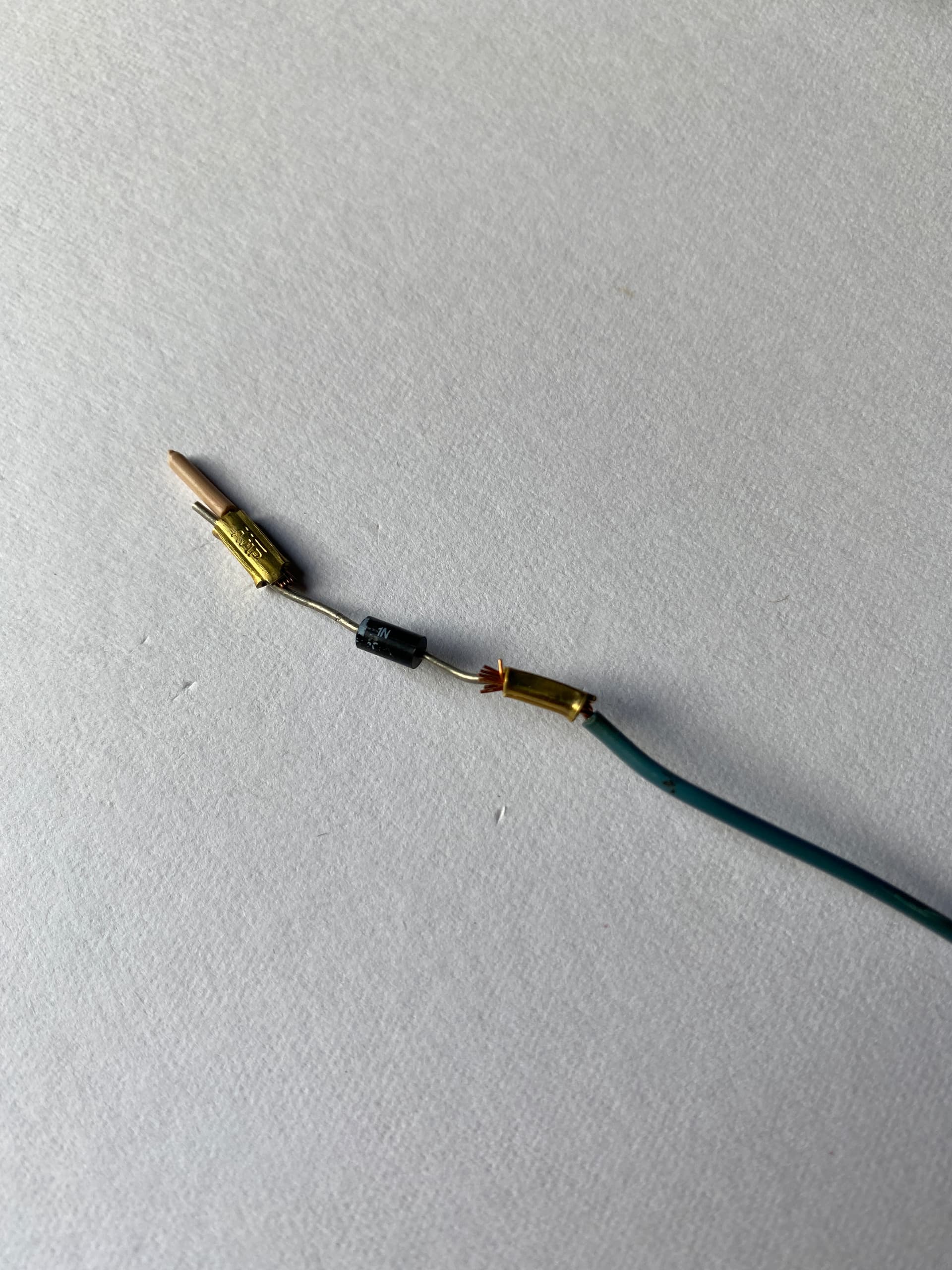
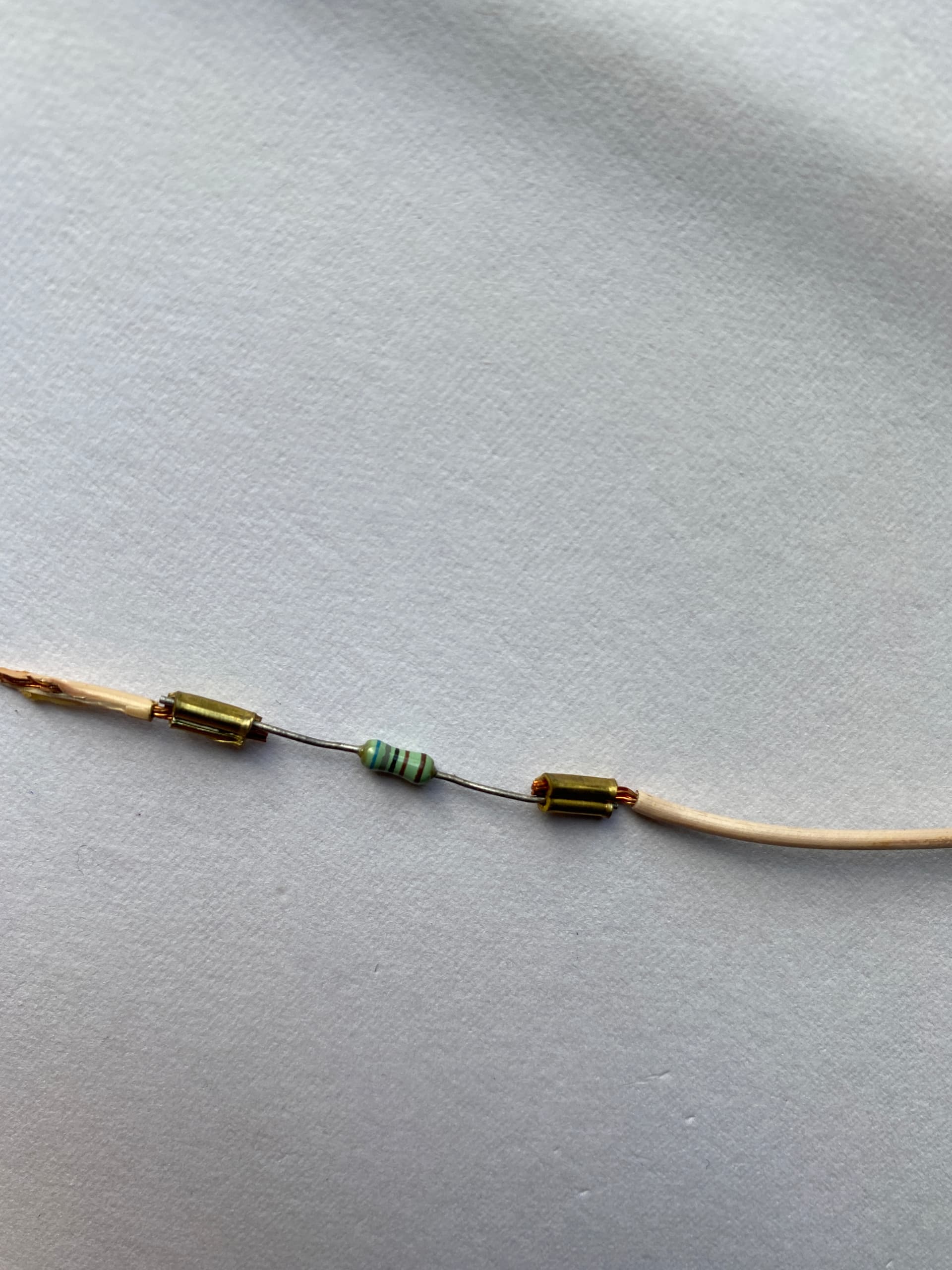
What is going on here, some sort of diode, but anyone have specifics?
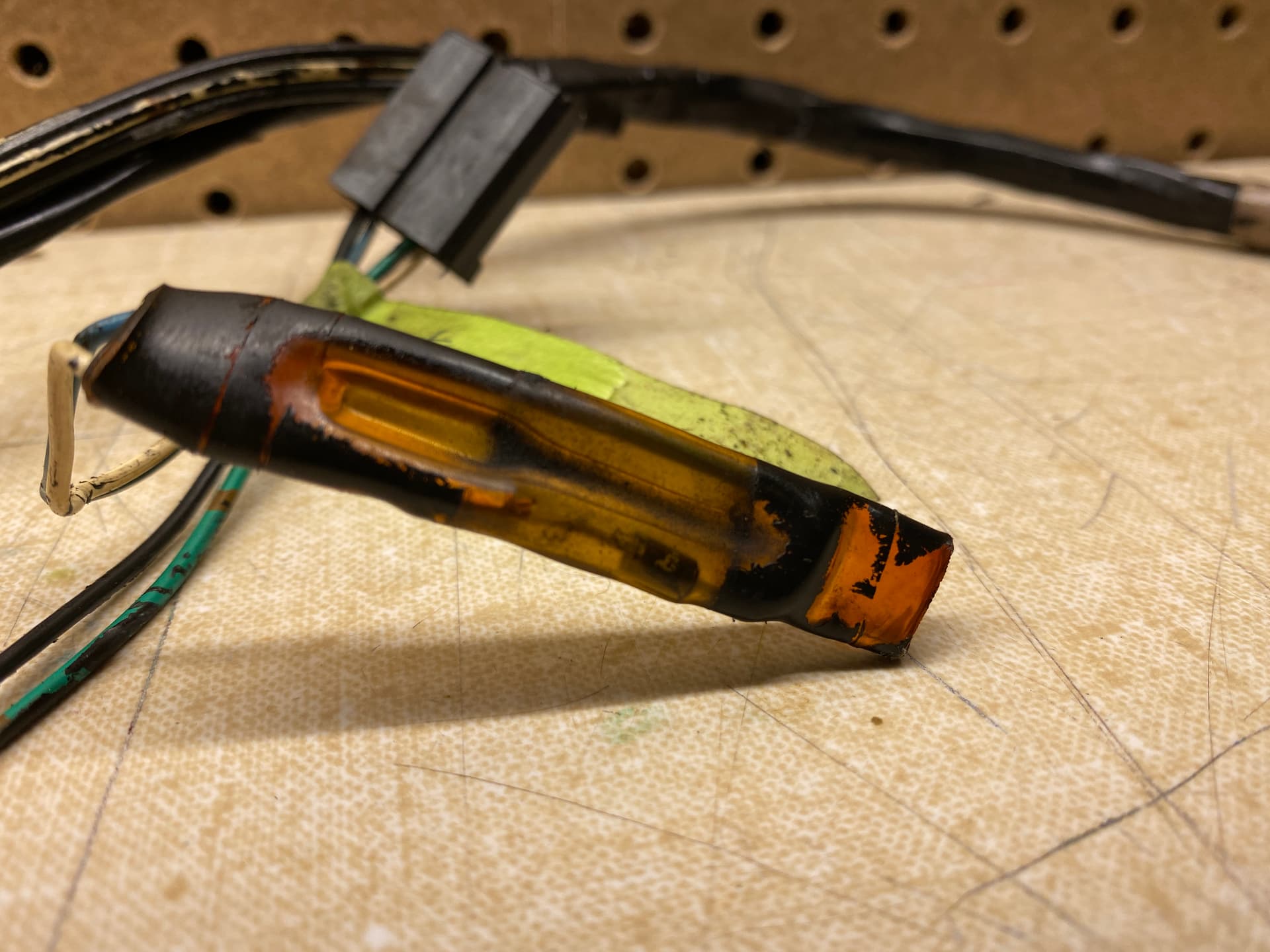
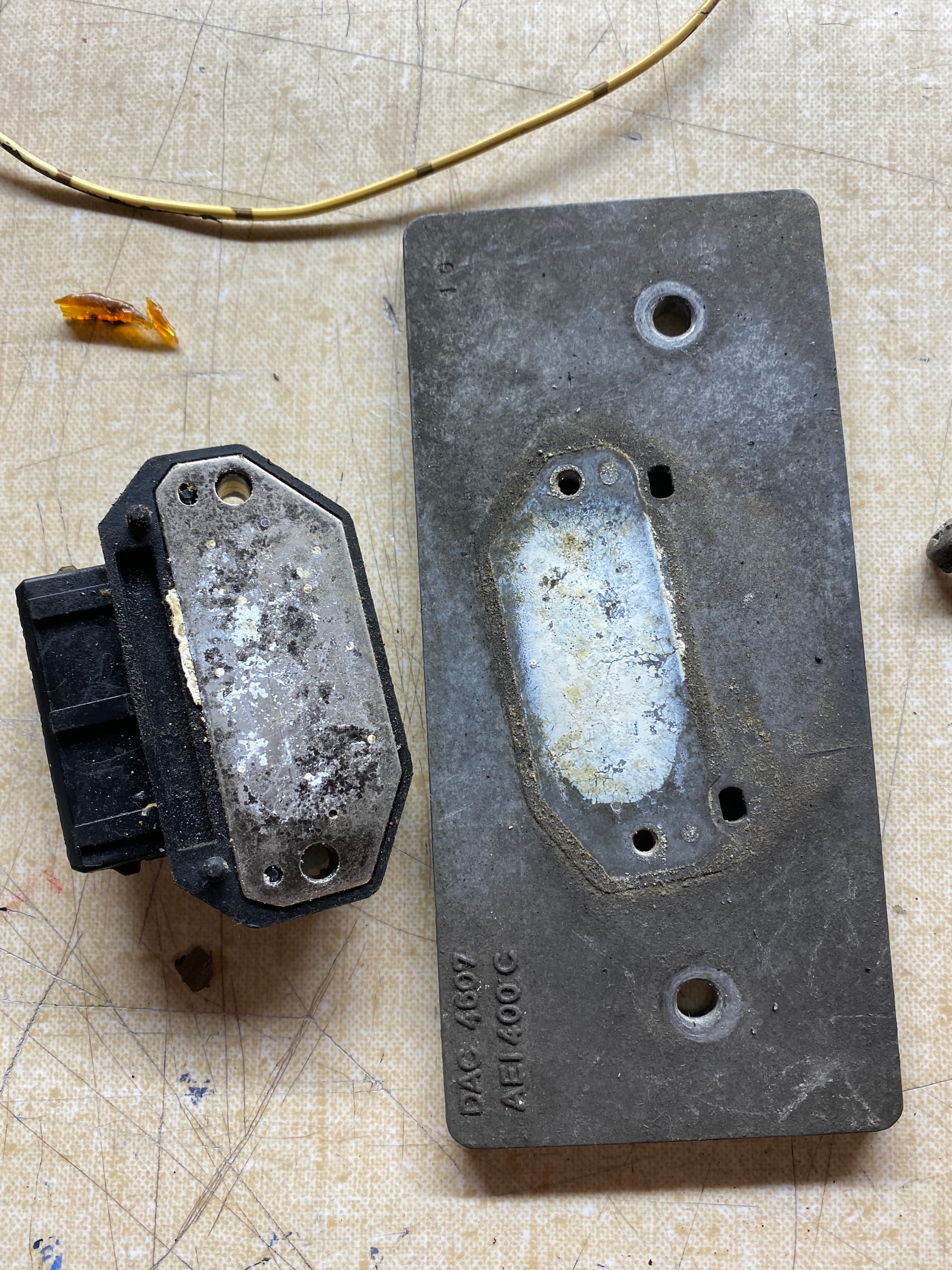
What was the idea behind mounting the power modules on the radiator support, do the aluminum plates serve as heat sinks and they put them there for airflow?
Heatsink indeed, but the problem is the aluminium plates corrode underneath so very little contact to the rest of the car. Take of, clean and reattach (possibly with some thermal paste for full effect).
I’m liking thid but where will you get all the colourfully colour-coded wires from?
I’ve got gxl wire in a variety of colors. Colored heat shrink or I have 3m ScotchCode wire marking tape for the secondary color that I’ll use at each end.
It looks like the PO might have already had some thermal paste on the power modules, but I’ll clean up and reassemble with fresh. The reason I asked was I was thinking of relocating these just because they are kind of out of the way and I was looking to reduce the the length of wiring. I’ll leave them there for access to airflow and probably reroute the wires along the right fender instead of right above the exhaust manifold.
Demonstrated here on a very easy part of the harness to split off from the rest - fuel rail temperature sender. Wires heading along the fuel rail to the rear bulkhead. I’ll terminate with a 2-way weather pack replacing the 4-way green sumitomo (the other two into this connector are the shielded wire connecting the efi ecu/diagnostic socket/ground and the ignition ecu. Someone tell me why they decided to make that connection in the engine bay. That connection will get its own 2-way, I think.)
On to the choices:
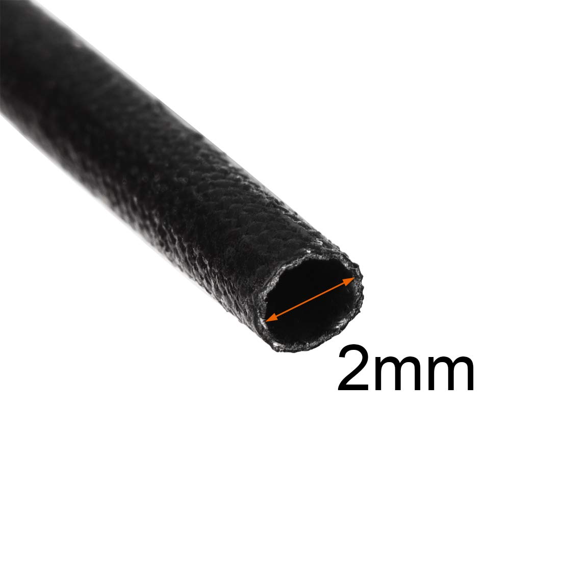
Expendable braided (I have a lot of this in a few different sizes). I’d use adhesive heat shrink tubing at the ends.
My vote for looks goes to the braid as it’s the most modern. My vote for function and protection would definitely NOT go to braid because it provides exactly zero protection, I would even go so far as to drip a bit of fuel, see if it melts?
What I have done is use the non-sealed heat shrink and only shrink it with heat at the ends- that way it can still flex as the wires can still slide inside of it.
Harness tape would be best for areas not prone to abrasion; a lot of current vehicles use this with only 50% of the harness covered. Saves material and cost. I used it a little differently, overlapping each wrap about 25%. It has no adhesive so harness is flexible (especially the way the OEMs use it). Just super glue the wrap at the start and finish of the wrap and only glue it to itself. This allows easiest branch offs.
Never use vinyl electric tape; harness becomes rigid and a sticky mess with oil or heat, and then the adhesive fails.
As I said, braid looks the best. But also as I said not sure what protection all those holes in the braid offer? In the first picture of the braid and cable you posted up there the braid is see-through towards the ends. But if the cable you’re using has good enough material for isolation then the braid is just cosmetic in which case go with braid.
There is a discrepancy on one year’s diagram. I don’t know why. It doesn’t really matter because the two channels for each bank are fused in the ECU so they actually fire in bank to bank batch as if the ECU only had one channel per bank.
Take another look at the 90-91 diagram. It’s ok. The injectors are in order, but note the connections are staggered. I think it was only the 92’ year that had the strange diagram.
Actually you’re exp is the first time that I know if that confirms the diagram is wrong. All other factors indicated such (no change in harness part number, — surrounding years being shown wired the same - staggered)…
See how 2, 4, and 6 are on one connection, and 1, 3, and 5 are on another?
Again, if you got it wrong, it’d be ok since they’re fired bank to bank. I’m guessing that if a connection went out, the engine would still run a bit more balanced on that 9 cylinders than just on 6 on one side and 3 in the back or front of the other? IDK.