I hate to confess my ineptitude but I am trying to troubleshoot a problem with my Harada power antenna (motor will retract but not extend the mast). How in the heck do you unplug the wiring connector from the motor:
It does not just pull out and if there is some kind of release tab I’ll be darned if I can figure it out. Likewise, how the heck does the signal lead disconnect?
Been a while since I was in there, but IIRC you either pinch that bottom tab or pull it back to get the white plug out …can’t remember how the other bit separates, sorry
Have you tried squeezing the sides together on the left side part of the connector? It looks like there is a groove visible on the inside.
I think on the white connector you need to pry open the little tab with the 3 ribs. Is There another tab on the other side?
Thanks Robin. In the light of a new day and better rested here’s what I learned: there is a release tab for the white wiring connector, just press it in far enough and give the connector a tug and out she comes.
As for the signal lead (black) connectors, they do just pull apart although I had to gently pry with a small flat screwdriver to get started.
The bad news is that after disassembling the whole bit, cleaning out the old stiff grease and regreasing with new, still no joy. The motor will run and retract the antenna but not run the opposite direction to extend it. Both up (extend) and down (retract) relays are good (verified with the covers removed and also by swapping them) so I’m at a loss. I have ordered a known good salvage unit so fingers crossed.
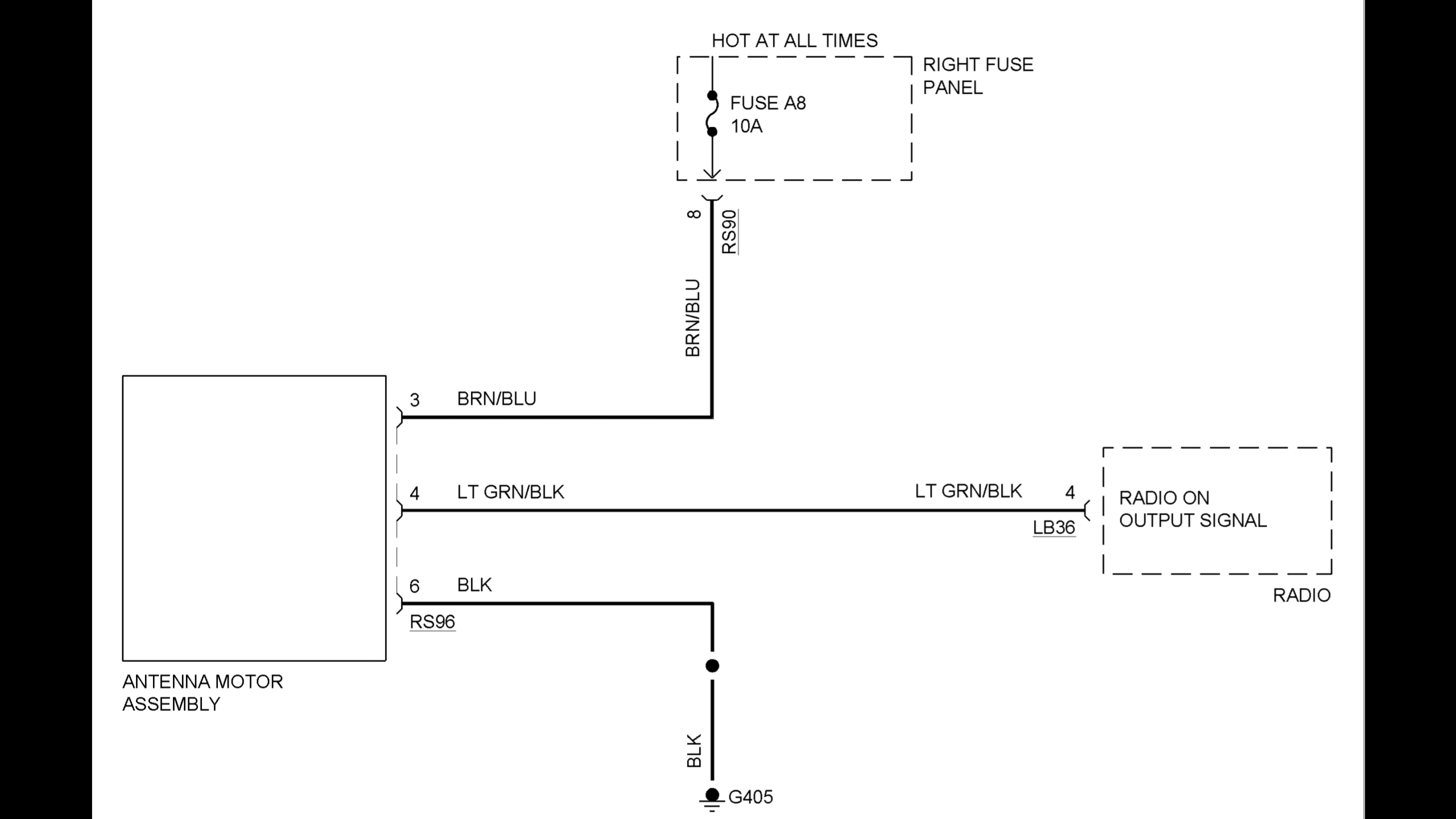
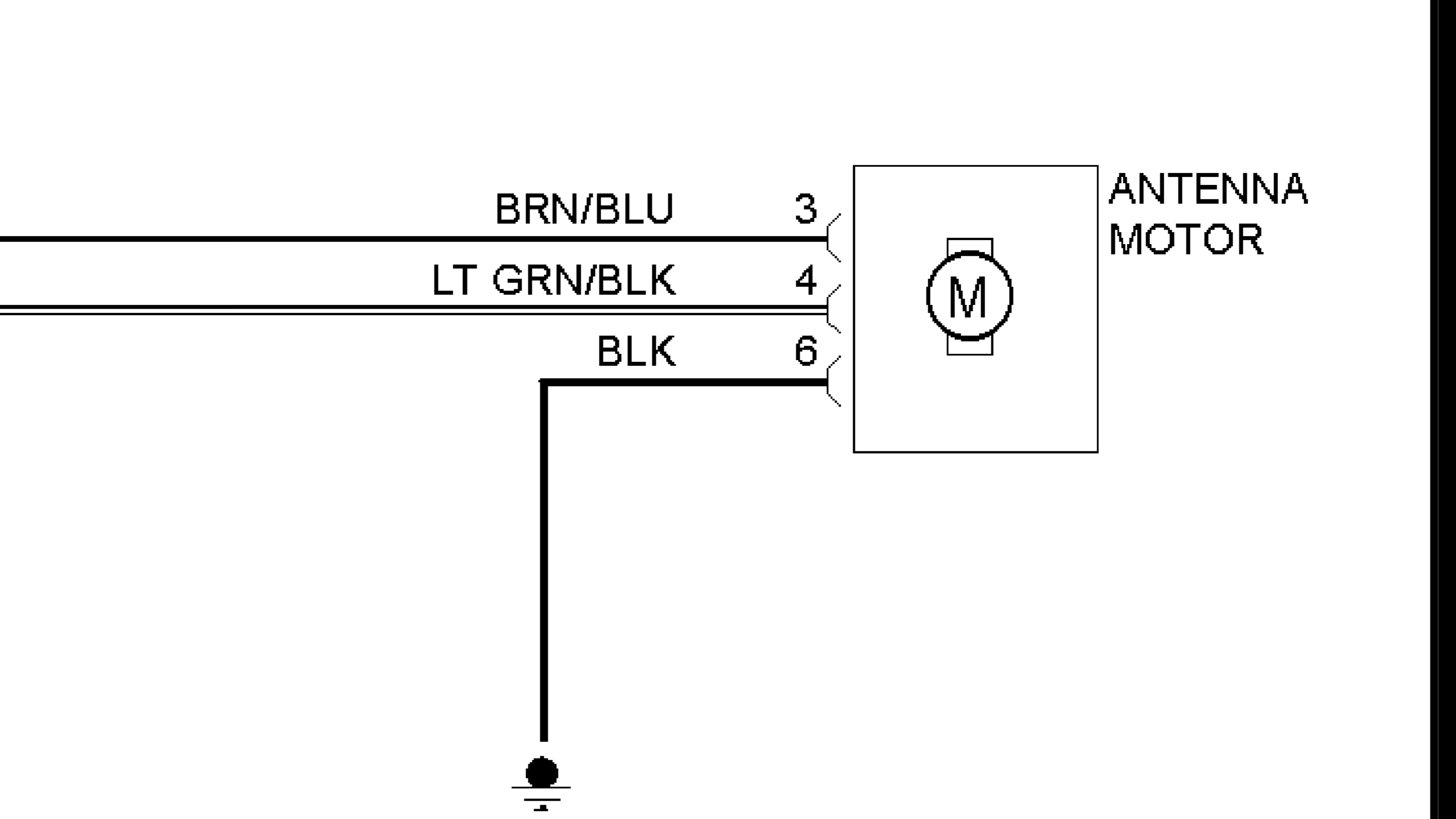
Update: still awaiting the replacement antenna. Re-reading my previous post my effort to troubleshoot this problem sounds rather weak. When it comes to electrical problems I’m no sparks but I am willing to tackle the worst that Dr. Watt, Professor Ohm, and the Viceroy of Voltville throw at me - if I have a few weapons (read: wiring diagrams) at hand. In this case, though, I didn’t have much with which to work. Two different wiring diagrams only show the three wires (power, ground and signal from the radio) that are in the aforementioned white connector that plugs into the power antenna assembly.
Inside the antenna assembly is a circuit board bearing, presumably, the magic jewels that translate the payloads of the power and trigger signal wires into the motor activity that should result in the raising and lowering of the mast. Info about the intended roles / functioning of the magic jewels? Zip, zero, nada, kein, nichts, diddly-squat. Sigh. Thus my decision to spring for a replacement unit. For which I’m still waiting…meanwhile, Happy New Year to one and all!
The replacement unit is installed and working correctly, so my original unit has suffered some sort of internal failure. The circuit board inside the unit is my prime suspect. I’ll report back if I learn anything more.