As a relatively new member of this much valued forum, this is my very first post. I am on a very steep learing curve and I would very much appreciate any help and advice.
Shortly after buying a 1948 MkIV 2.5 saloon (barn find) I discovered the Jag-lovers forum and have become a frequent reader of the interesting articles in the Pre-XK section.
I eventually made a start on the project early this year and decided to first strip and rebuild the engine that hadnt run since 1975.
I was very pleased to discover that, under the circumstances it was in surprisingly good condition. The engine number was not the original but it appeared to be a low mileage fully reconditioned later version engine (relatively little wear / mileage) having, for instance, steel con rods, std size 4 ring pistons and auto mechanical ignition advance.
However, during the strip down I was surprised when I removed the tappet blocks and discover what appeared to be a pressurised oil gallery. to nowhere. At first I though it must feed oil through to the tappets but there were no drillings in the block or tappets.
I have overhauled an air cooled engine that had hydraulic tappets that has corresponding drill holes in the tappet blocks feeding through to the drilled tappets and oil is then fed up through the hollow pushrods to the drilled valve rockers.
Confusingly, 9 of my 12 pushrods are also hollow and drilled (you can blow air through them) but the other 3 are completly sealed but neither the tappets or the rockers are drilled anyway, so whats the point?
I do have a reproduction Service Manual and altough it has an exploded view of the 1.5,2.5 and 3.5 engines, the tappet blocks and tappets are nowhere to be seen…
It also shows the pushrods with (cussion?) springs and drilled rocker arms with wicks but my rockers are completly solid so no provision for any wicks.
I would be very grateful if anyone could shed some light on my findings, especially the pressure fed tappets blocks with the mystery oil galleries.
The push rods are lubricated from above via the rockers. I think all your push rods should ideally be either hollow or solid but not mixed simply for reason of engine balance. You have alien rockers as they do need to be drilled and restricted by wicks.
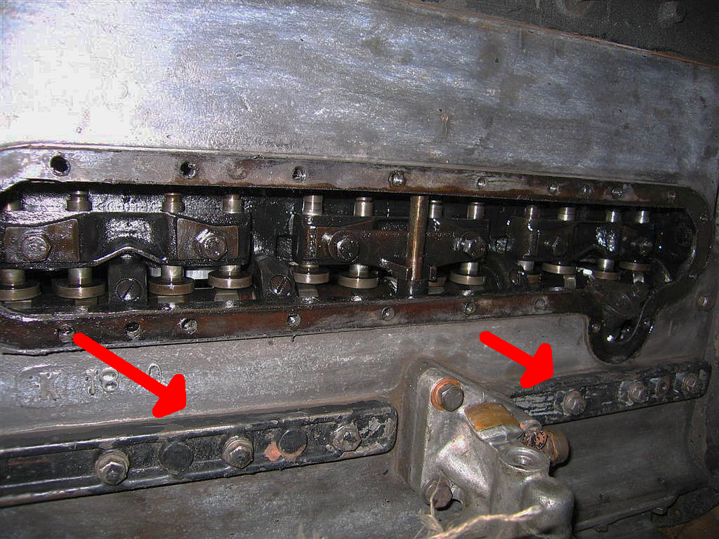
The main oil gallery is accessed by removing the plates arrowed below.
Thank you for your much appreciated and interesting reply and I apologise for waffling on a bit.
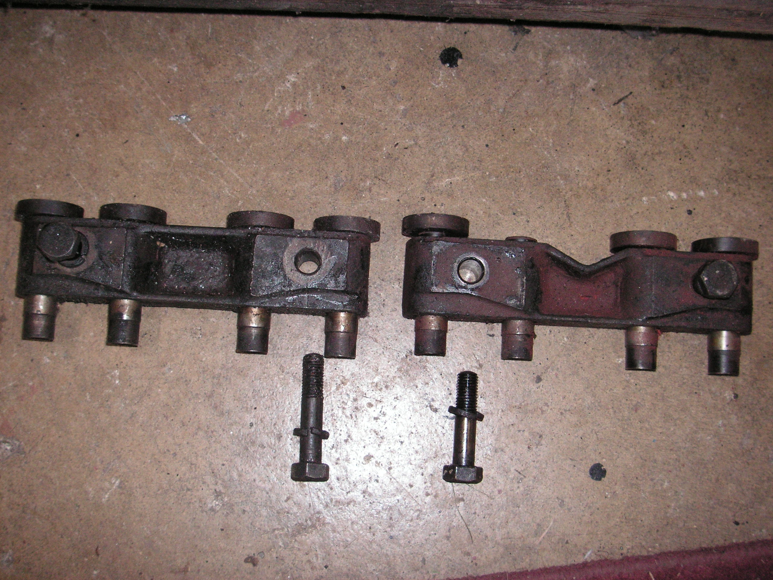
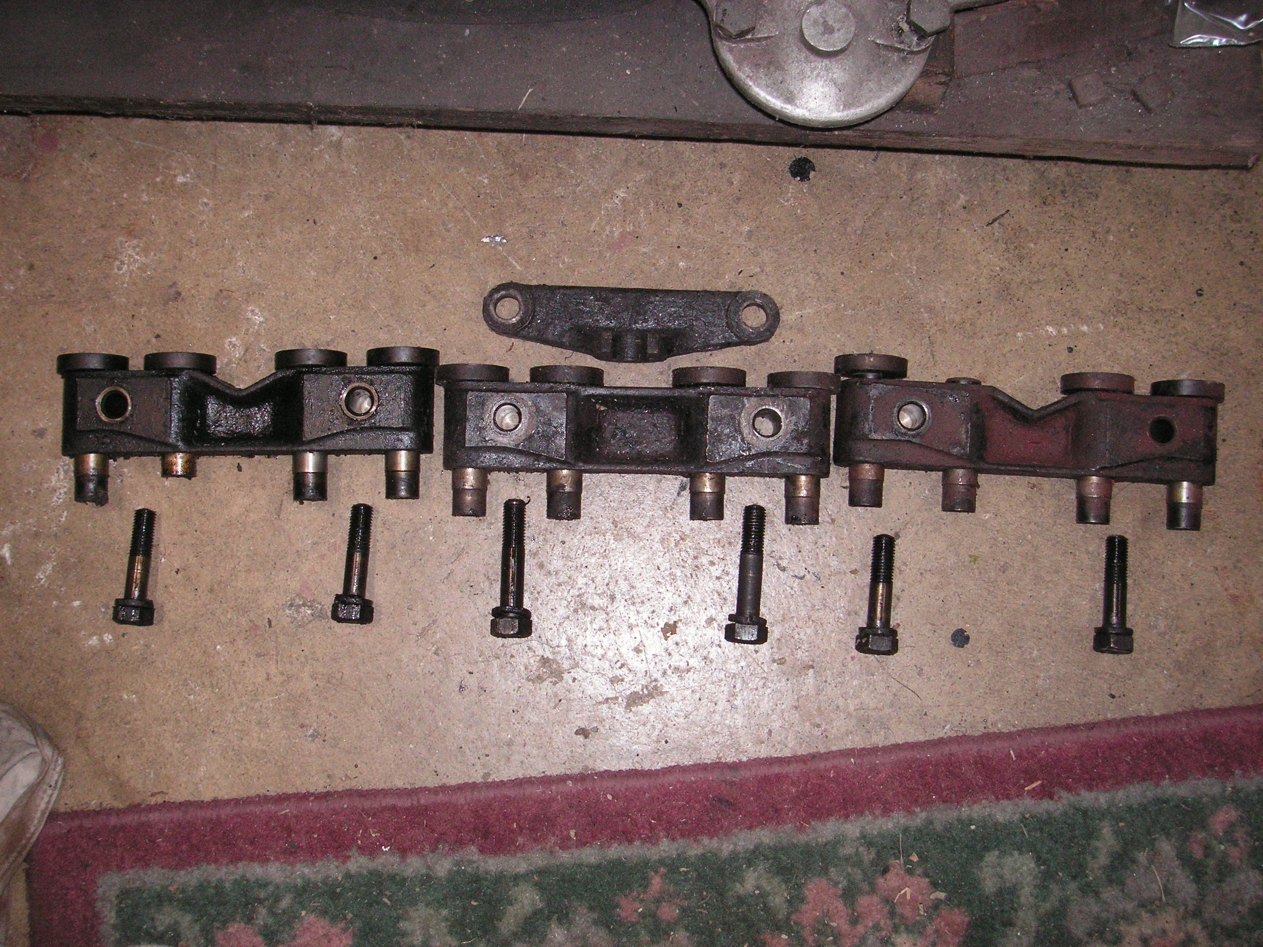
With regards to the tappet blocks, I think I should take a couple of photograph of them to help me explain better (worth 1000 words).
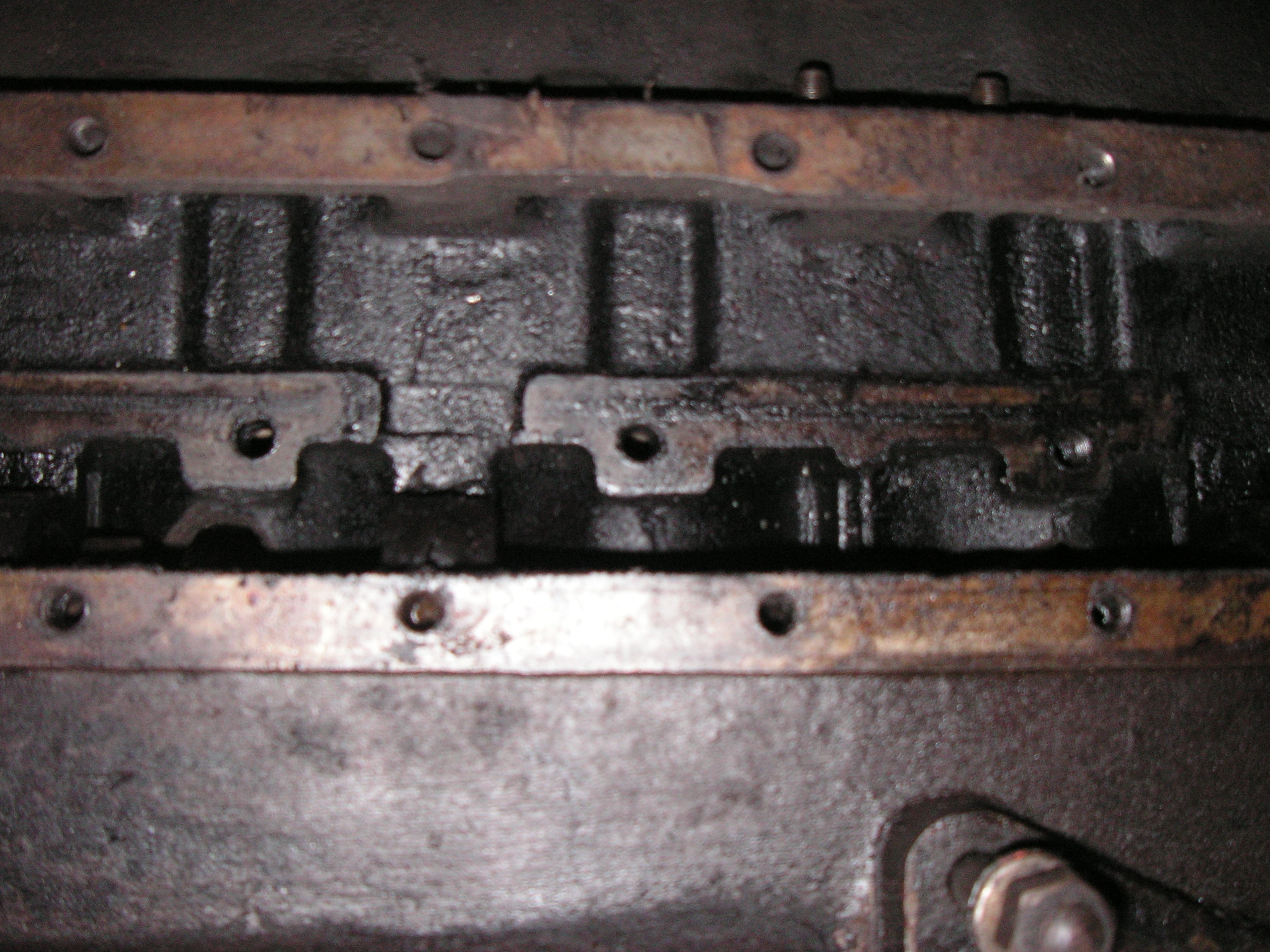
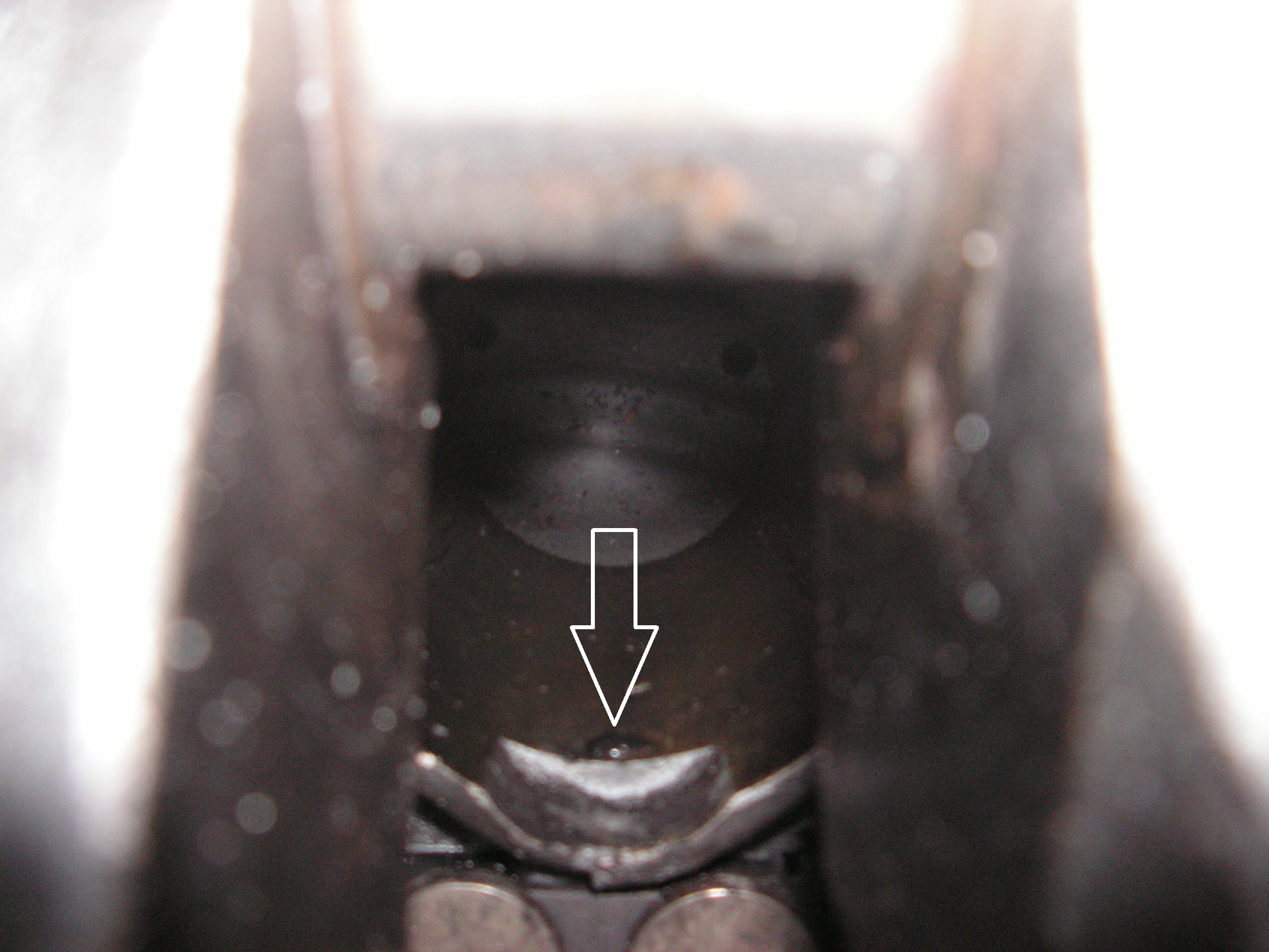
Each of the three tappet blocks have a longitudal channel cast into them and these corresponds with small oil supply holes in the crancase. Pressurised oil is supplied to the three drill holes via main bearings but the channels in the blocks are not drilled and therefore the oil has nowhere to go, other than leak between the tappet blocks and crancase machined surfaces (no gaskets)
I will take a couple of photos and try to work out how to include them in another reply.
I am at the point of re-assembling the engine but I’m reluctant to blindly re-fit the tappet blocks until I have solved the mystery.
Hello John, the oil flow is via external oil line from the oil gallery plate up to inlet in cylinder head which then feeds into the rocker shaft where the oil is distributed to all rockers with subsequent partial dribble down the pushrods to the tappets and cam. You also will benefit from having a parts manual (e.g., see Oil Pipes details listed for 2 1/2 litre engines on page 6 of the parts manual.
The very most important thing to remember about the tappet blocks is that the long bolts OLY go in the centre block, the shorter bolts to the front and rear.This save buying expensive pistons later.
I have a 3.5 Mark V engine at hand to look at, and the tappet blocks on this one have the groove on the back, but no holes through to the tappets, and no holes in the block from which to supply oil. The push rods also have no hole through. Near as I can see, the tappets get their oil from whatever flows down the outside of the pushrods.
My first inclination is to suspect you have a bitsa-dis-bitsa-dat or mix-n-match engine. It is sadly not uncommon with old Jaguars.
In comparing the parts catalogues for 2.5 '38-46 and 2.5 Mark V, it says there was a change in the part numbers of the tappet guide blocks from C.433 and C.434 to C.433/1 and C.434/1. The same change occurred with the 3.5 engines. But there is no explanation given.
The Mark V manual, which is a little more thorough than that of the Mark IV, says nothing about cleaning any oil passages to the tappet blocks.
The wicks were at the valve ed and the end of the rocker arm was soldered over.
If you put that end of the rocker u against a wre buff, it willremove the slder and you can see the outline of the hole.
it needs to be drilled out to 1/8" right through to the hole for the bush , and the other end cleaned also [ 1/16" from memory.
The felt is white engineers felt cut to 1/8" x 1/8" strips.
If the rockerarms have a C*** part number moulded into the side they are Jaguar and have awick
AS Peter says, The pushrod weights should be the same. easy enough to weigh them
If you have the cam followers out check the faces, they should not have any pits and put a straight edge across the face… It should not be flat but have a radiussed crown in the centre of about .002" . This is to help it revolve and not wear in one spot.
I was aware of the oil feed to the rockers thanks Roger but I will certainly get myself a parts manual.
I can see how the wrong size bolts would do the damage to the pistons thanks Ed.I think its a case of “if it can happen it will happen” Re the rockers, I hadn’t got as far as carrying out a full cleaned up inspection of the rockers but after what you said, I cleaned one of them and lo and behold, they do indeed have solder in the pad ends. I understand that they were sealed to prevent excess oil from overwhelming the valve guides which can lead to excess oil burn (probably only the inlets) but you seem to recommend I drill them out. I also believe the Jaguar wicks are not easilly available. Thanks Ed.
It was very interesting to hear about the change in the tappet block part number Rob. The fact that you have the grooves in the tappet blocks but no oil feed holes is very interesting. I’m not sure if my engine was and earlier or later type but for what its worth,my engine number is P675 but the doccuments show the original as P1032.
When I work out how to load photos onto my post I will send some showing the drill holes. These align with the grooves but as you say, the gorrves are not drilled, so the sysyem appears to be quite pointless.
Thank you again to everyone. I didnt expect such a great response.
Thats a very kind offer Ed, thank you. I will be stripping the rocker assembly down shortly and it will be interesting to see what I find. I have overhauled a few engines over the years but this arrangement is another first for me. You live and leard…Thanks once again.
Curiosity overwhelming me, and wanting to kill kitty cats, or at least examine more closely an already dead cat, I had a look at a 3.5 Mark V Z engine block. The Mark V manual says this matter of the long screws only applies to the 2-1/2 liter engine, not the 3-1/2. They have C part numbers so I can’t tell the correct length from that.
I measure the screws as 3/8-20 BSF x 1-5/8" and 1-7/8" long hex heads. So C.425 is the shorter one and C.426 is the longer one.
I see the tapped holes for all 6 tappet block screws are tapped through to the cylinder bores, and where the holes in #3 & 4 are on center, the holes in #1 2 5 6 are offset about a bolt diameter. So in each case you don’t want to use a too long bolt.
However, it was not obvious to me as to why they would be different lengths. The tappet blocks are all the same thickness and the mounting surface is all one cut.
Nor can I see why to use the longer one in #3 & 4. It must be something different about the 2.5 block which I can’t determine by looking at a 3.5 block.
Hello John, since you are down to tappet blocks out, you might be examining cylinder bores as well. If so, consider having the tappet blocks installed and properly torqued for cylinder bore measurements and during re-bore. That way the effect of the bolts pulling on the block is included.
It was interesting to hear that you have a MkV engine Bob because I was beginning to think that my none original engine was from a MkV but that doesn’t fit in with the numerically lower engine number, P675. The number on the Heritage Certificate is P1032, suggesting the one I have now is an earlier unit.
Another spanner in the works is that my central tappet block has an additional cast bracket with a “U” cut out in it to accomodate the rev counter drive shaft. Again, I have taken photos but I’m blowed if I can download them onto this page, because they would really help ( Im working on it though). This bracket picks up on the two bolts and its depth is equal to the extra length of the center bolts. That explains why these bolts are 1/4" longer than the other 1 5/8" bolts.
So, combine this with that fact that some blocks have a pessurised oil feed to the seemingly pointless groove in the tappet blocks,adds to the mystery. And why did they continue to fit longer bolts to the centre blocks that didn’t have the, as yet, unexplained bracket attached?
Interesting point about fitting and torquing the T Block bolts prior to re-boring the engine Roger but fortunately I have near perfect STD bores, so lucky me!
The diagram showing the possibly bolt penatration into the bores was also interesting Peter but again, why continue to fit the longer bolts to the 3 1/2’ engine?
Thank you for taking the time to take photos and suppy diagram, again very much appreciated.
I cant believe that I am the first person to identify these, as yet, un-explained anomalies.
I am now approaching the the re-assembly stage and my dilemma is - do I re-fit the tappets as I found them, as there was no evidence of a serious lube problem to the tappets, or do I plug the three (pointless?) oil feed holes? There were no gaskets fitted between the crankcase and tappet blocks, so some presurised oil must leak out, with a possible effect on the pressure.
Ed has very kindly offered to send me the wicks for the rockers (I think Worcester Spares sell them but I;m not sure if that is only if you buy a rocker gear overhaul kit) but could anyone explain why some are drilled and some sealed. Im tempted to drill them but if it effects the oil consumption, I can always re-seal them I suppose.
The end of the screw is protruding a very slight amount, but enough to be hit by the piston if it goes down that far.
So clearly the caution should be applied to the 3-1/2 engine as well.
(Flourish of cape and waving of magic wand while shouting Ta da)
And here is the reason for the short and long screws.
The tachometer drive shaft support on the #3 & 4 screws. In the parts catalogue it seems to be called C.427 Abutment, Steadying Shaft and listed with oil pump shaft parts.
So if you put a short screw where a long one belongs, the tappet block will be insufficiently supported with possible breaking of those two bolts.
John, a P engine is certainly correct for '46-48 2-1/2 Litre Mark IVs. They began with P18 after the first 17 cars got leftover pre-war L engines. Allan Crouch says they ended at P1899.
Mark V 2-1/2 Litre engines began with H2001.
To upload a photo, first set your cursor where you want the photo in your message, then click on the icon that looks like a VHS tape with an up arrow. It will ask you to Browse, to choose your photo from where you have it stored on your computer. Click on the photo file, then click Upload.
Ahh, I see John figured it out as well about the long bolts.
On the rocker arms, it is possible that some of the plugs fell out. Some are missing on this derelict engine of mine.
For the first few years after the war there was a factory engine exchange program for rebuilt engines. It is possible yours was part of that program.
Anomalies? I haven’t kept count but we’ve probably discussed at least 100 over the years.
The bracket on 3&4 provides end float control for the cam to oil pump gear.
The 3 1/2 engines do have this.
The original pistons were 4 ring T slot. Not that strong but quieter. So maybe with the 4th bottom ring there may be some point in torquing… or not. But I always use 3 ring solid skirt pistons { ala XK] and the rings are far enough away for it not to be an issue.
I only brought the long screws issue up, because people have made that error in he past
If you are replying in the JagLovers website then at the top of the box where you write you will see a short horizontal line with an arrow pointing up.
Hit this.
This will bring up the screen where you can navigate to your photo.
Hit “Choose Files” and navigate to where you are storing the photo on your PC. Having selected the photo hit “Upload” and it should appear where your cursor was when you started the upload process.
The forum will resize your photo but if you have not resized it to a smaller size then your upload may take a bit longer.
Are the oil grooves you are seeing just spiral grooves in the sliding parts of the tappet? I can’t remember if there are any but if there are they are not connected to the pressure feed and just rely on the flow coming down the push rods.