No spiral grooves on my tappets.
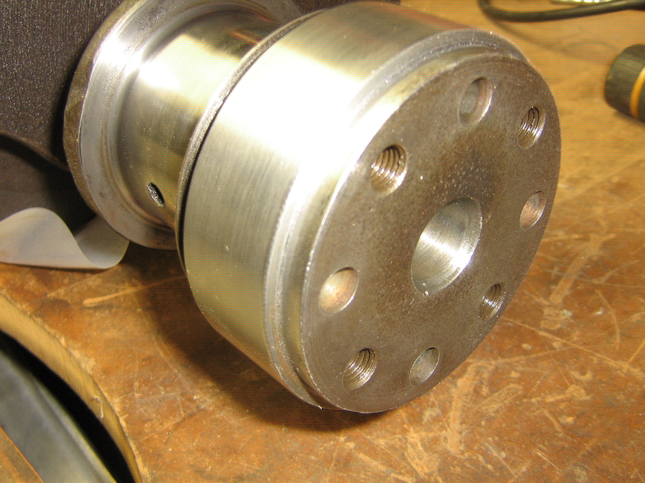
Here is the mystery groove under discussion.

One begins to suspect it is a legacy from the Standard days.
No spiral grooves on my tappets.
Here is the mystery groove under discussion.
Good thinking Rob,
As a side valve there will be no oil supply from above.
Peter ![]()
Looks like it was fed at the cam bearings

Thank you for the advice on downloading photos Rob and I hope you are now able to see the small oil feed hole. this feeds the number 1 & 2 tappet block but to add even more confusion, the oil feed hole that feeds the 3 & 4 tappet block is almose twice the diameter as the other two.
Prior to receiving all the valuable info from you all, I now realise that I was wrong to believe that my relatively low mileage engine with std size bores, split skirt 4 ring pistons and steel rods, was possibly a slightly earlier unit that had been reconditioned and updated during the process but from what Ed says, the 4 ring pistons were fitted to the earlier types.
I read somwhere that these pistons with steel rods are identical those in the 1 1/2 litre so I led myself to beleived that this combination was possibly a later design.
It would be interesting to know when Jaguar decided to abandon this oil feeds and why only the 2 1/2 litre’s needed the bracket fitted to the 3 & 4 tappet block. The bracket fitted to my engine in very similar to the one on your photo Rob but it appeared to be missing from the shot of the assembled valve blocks that Peter sent earlier.
I’m not sure about the “spiral grooves” you mentioned Rob but the grooves in my tappet blocks are practically identical to those in your photos but my grooves are not as close to the bolt holes, so there is a slight design difference there.
The side valve theory sounds very plausible Peter but comparing the cross section diagrams you posted, you can see (as you pointed out) that the SV engine tappets appear to receive presurised oil from the camshaft bearings, whereas the OHV engine,appear to receive oil from the main bearings, as I confirmed on my engine.
Does anyone have a view on whether or not, I should block off the three oil holes? or is it a case of “if it ain’t broke…”.
A big thank you. John.
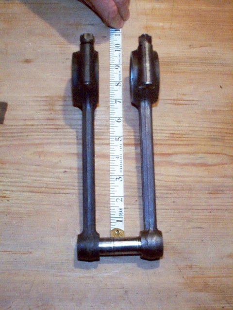
The rods are identical, there is a difference in for /aft offset… It can be fiddled, but you would need to find 2 sets for donors and they’d need to be matched sets.
The 3 1/2 litres also had the bracket on the tappet block
I have never seen spiral grooves in the tappet blocks
The factory may have felt later that there was enough oil running down the pushrods.
The cam follower in the pic looks a bit corroded, what condition is the face?
If you are referring to my rusty tappet or lifter, there is not really any hope of that engine ever running again. You’ll notice in my earlier shot that one of them has completely lost its head. It may have ended its life down in the sump with all the bits of exploded piston.
The oil groove in the back of the tappet block appears to be a feature of the raw casting, so was probably deemed not worth the trouble to eliminate from the casting pattern, but at some point they eliminated the hole drilling in both the tappet blocks and the engine block.
This group loves to delve into these obscurities.
Hi John,
The larger diameter feed hole in the centre might be on account of the pressure differences at different parts of the system. For example the big end bearings are fed from an adjacent main bearing and each main only supplies one big end except for the centre main that feeds two.
I don’t know the purpose of the bracket although it was also fitted to the side valve engines. I can see it in the photo I posted with the two big red arrows in it although it doesn’t appear in the cross sections simply because they were not cut on the centre line of the engine.
As Ed points out, the 1½ litre rods are very similar to the 2½ litre steel rods except that the big ends are offset lengthwise on the crankshaft so if you want to fit them to a 2½ litre engine you need to grind off one side of the small end in order to give clearance in the piston. The 1½ litre rod is on the left.
Peter
Hi all,
Thank you for all the valuable information on this topic.
The advice received has helped to explain some of the anomalies and although there appears to be no official reason for the extra oil feed holes and channels, However, I’m now convinced that they are a redundent feature and I can now assemble the engine knowing that my tappets are unlikly to seize due to lack of oil.
With regards to the steel con rods, I also rear somwhere that the 1 1/2 litre’s had the steel rods but as your photo shows Peter, they are slightly different but could be modified to fit the 2 1/2.
I was so relieved when I discoved that I had the steel rods fitted as this saved me around £1800.00!!
I can think of several more questions for the group, ranging from, for example, the modifying the rear crank oil seal to a lip seal and fitting electronic ignition, to name but two.
Regards, John.
I certainly wouldn’t recommend modifying the rear crank seal
Firstly As compared to an XK engine, thepushrod cars have a much smaller breather, but the slingers fr and rear on the cranks do provide somepressure relief. Slingers are not necessarily inferior, Honda used them on their F1 engines.
People often assume thatbecause they find oil leaking under the fr and/or rear mains, that the slinger must be leaking, when in reality it’s more likely to bethe poor design of the aluminium blocks underneath each. Part of the poor design is threading fine thread sump bolts ito thealloy. An engineering no no. They should have stud s into alloy, which is basically what we do The studs need to be well sealed as the thrad hole runs into a cup at te top, ideal for collecting oil to run down the thread while the car is parked
Then there is the needless and unused extra horizontal holes in the blocks.
one of these engines is never going to beil tight in a Toyota sort of way, it can be minimised
The other aspect of seals is that wave seals can have issues at high surface speeds, The rear axles have wave seals but they are smaller and run at about 1/4 of the revs. I recall a NZ friend with a n SS DHC who went to much effort to mmake modified seal holder for the rear main. Of course now these cars are not driven as regularly as a modern and so the seal stuck to the crank, And replacing it involved, floor , gear box etc etc out. At least when a pinion seal goes[ and they do] it’s easy to access.
I am also unsure of the practical advantage of electronic ign in one of these. I have run Lucas distributors on these for about 40 years on a number of cars without great problems
A friend put an electronic [ and expensive] system ona car with the DUH6A dist and found no improvement. The single issue[ apart from wear] on the DUH6A { SS} distributors is they relied on earthing through the2 screws that hld the bakelite base to the body. Thisis a bit unreliale as an earth and Lucas later changed the base to incorporate a separate earth terminal on the side for a positive earth.
+1
…and I’m a retired electronic design engineer.
Peter
Very interesting to hear the comments on the cranks seal mods and I was relieved to hear that I could be wasting my time (and money) trying to modify the rear seal, when the main problem is elswhere. I will certainly spend some time trying to reduce the oil leaks as suggested, and replacing the rear sump bolts with sealed studs sounds like a good start.
I havn’t invested in a lower engine gasket set yet, mainly because I was shocked at the price, or is there more to this set than I imagine.
It will probably be a week or more before I concentrate on this area of the engine but I have seriously considered making my own gaskets,using the correct gauge material. I havn’t made any for a number of years but I still have the necessary tools, but any advice on a more suitable material for replacing the wedge shaped seals fitted to the end of the alloy end plates, would be much appreciated. Were the originals made from cork?
With regards to electronic ignition, I agree that the old Lucas system was reliable but it certainly wasn’t maintenance free and of course, any mechanical wear, including the points gap variations, would effect the timing and general performance.
When my engine is eventually running I intend to stick with the original Lucas system, if only to monitor the performance over time but I may be tempted to fit one of the more discreet electronic systems later.
My 1948 engine / distributor has centrifugal advance but I believe the MkV engine had the vacuum advance units fitted but I havn’t yet found any date on the combined maximum advance in the cruise.
In my earlier life (1960’s) I operated a Sun 1020 engine analyser and I was aware of the benefits of having correct ignition advance and the effect on performance and economy, not to mention a cleaner burning engine.
I believe the benefit on economy may be no more than 15% on a good day, which in Imperial MPH could be no more than 2 to 3 mpg but bearing in mind the octane rating of fuel in the 50’s was only around 75, then there could be some benefits, if only to improve the overall efficiency, which I believe would allow the engine to run a little cleaner with, for instance less cylinder wear.
On a similar subject, could I ask your views on the valve seat situation with lead free fuels?
There are of course fuel additives and you could do a mix with 100LL aviation fuel but I have heard that it is not recommended to fit hardened exhaust seats due to the proximity with the inlet seat. Looking at my cyl head, they do appear to be quite close.
John.
Using an electronic ignition, like a Crane or Pertronix, has little downside: it will be an improvement over even a top notch p&c system, and totally reversible.
Hi John, the parts and service manuals are wonderful in original or reproduction print versions but also are very helpful to have an electronic set in portable document file (pdf) format. The Compact Disc has been available for Jaguar and maybe Jaguar Heritage Trust. We might be able to get you a copy if those sources don’t pan out.
You may be amused to learn C.321, Piece, Filling, for Front Sealing Block (part A.6 on plate A) and C.322, Piece Filling, for Rear Sealing Block (part A.8), that all four of these pieces are wedges of wood. These come in some gasket sets though you could make your own easily enough. Are these the parts you wondered might be cork?
My experiences with valve seat recession is observation of essentially no recession observed in my nearly 20 years of lead free fuel use on my Mark V 3 1/2. Engine rebuilt a couple years ago at 120,000 miles, I’ve driven it about 13,000 lead free miles in my ownership and it lived its whole life in California where lead free happened decades ago. I’ve only heard of valve seat recession occurring when high rpms were maintained over extended time (i.e. race cars) and my car is not raced. There isn’t much room for putting valve seats into these heads. I figured if there was no evidence of recession, no change was needed. The shop which machined the head agreed there was no need for complicating a well-functioning situation.
Correct that Mark V has vacuum advance, in fact the same part as used on XK120 so readily available from XK parts sources.
There has been much discussion about the Pertronix on the XK forum over the past dozen years, with positive and negative opinions. And at this moment there are threads open on the XJ and Saloons forums on the same subject, people having problems with them.
For a Mark V it would use the same parts as XK120, but I do not know about earlier distributors.
Hi John
I have cut a set of gaskets for a 3.5 motor recently & there are no dramas, just time consuming. Measure the old thickness of the original gaskets & then buy the sheets of gasket paper from your auto store. Use Permatex, Holomar or a good auto silicon & the gaskets will be fine. Head & exhaust gaskets are better bought. A word of warning, I cut a sump gasket a couple of years ago & when I went to fit it recently it had shrunk longitudinally, not happy.
Re the wooden filling wedges I squirt some black auto silicon in the slots & then feed in then ram in thin asbestos rope or the modern equivalent with more silicon. Keep doing this until the slot is full then cut off the excess rope. I learn’t this process from a old timer who was a guru on big Healey engines. I don’t know how hard it is to remove but it works well on my Healey.
Cheers Peter
yes gaskets can mostly by cut from gasket paper using the old wad punch and ball pean hammer technique.
We had the factory drawing of the sump gasket and had it lasered out of 6 mm steel which makesa good template to cut them. TRouble is, of course that the sump shape alone, i wasteful of gasket paper.
Old gasket papers can shrink through drying out
It’s worth thinking about bore size when ordering head gaskets, These days engines arecommonly taken out beyond factry over sizes. and the crush can end up inside the combustion chamber.
This can also happen because reconditioners sometimes didn’t rebore the block central to the original bores. Bores wear more on one side so it was seen as a way to keep the over size down.
One can’t mix silicon against permatex. Doug opines that a sump gasket with silicon either side will allow movement from the different co-efficient of expansion twixt alloy and cast iron
For the rear slinger one needs to use a feeler gauge to centralise it. And if rebuilding on an engine stand , modify it so the bolts can be installed before the sump
The front timing cover needs to have a tapered piece made to fit over the crank nose to hold it cetral while the bolts are done up.
John, fitting lip seals etc is my preference. 25 yrs ago i fitted a rear crank lip seal on my engine but not a front
lip seal. I recently removed and dismantled said engine and will ,including other work, convert to a front
lip seal. Removing the clutch/flyweel revealed that the lip seal is effective, the rear of the engine being
bone dry. 25 yrs ago my method was to build up the alloy housing with weld to enable it to be machined
to accept a seal, but now my method is to use a Mercedes seal with a adapter plate., some photos are
posted on the SSdata web-site check chassis T249362.
Regarding the rocker/ wicks, I removed the solder and old wicks, cleaned out the crud, resolderd the rockers
ommiting the wicks. Oil control down the valve guides is achieved by machining the guides to accept
stem seals Photos show a guide machined to accept a stem seal and the required sleeve fitted to the
crank for the lip seal.
Conflickting advice re these mods is, of course, expected it just comes down to personal choice.
I know what works for me.
Re camshaft. Recently my cam lobes were reground to original spec by Kent Cams at the price, inc postage
of under 200 sterling. There are two profile types, long and short duration, mine is long duration,
not sure if Kent cams can grind the short duration version.
Peter B.
These engines are extremely tolerant of ignition timing. As to valve seat recession don’t bother. Just use basic unleaded. The MkIVs do actually have separate seat inserts. Don’t mess with them and risk machining where there is precious little material to play with.
Peter
Highly valuable information coming in thank you all. The Jag-lovers site is proving to be extremly helpful and beyond my expectations.
I emailed the Jaguar Heritage Trust today enquiring about the CD but I may need to come back to you on that one if I have no luck Roger, thank you.
Judging my their appearence I think the old “wood” seals in my engine need carbon dating. It would be interesting to see an original one but I’m sure a more suitable material is needed and the suggested asbestos rope trick with Permatex may well be the answer, so thank you to Peter / Roger for that nugget of information.
I bought gasket paper of various thickness recently, so I will attempt to make the lower half gaskets. I bought a top end set quite recently that included the preferred 0.010" thick copper head gasket. Ive been advised to use Wellseal for this.
There was a label inside advising you to soak the cork rocker cover gasket in water if it had dryed out and become mis-shaped.
As much as I would like to attempt a lip seal mod like yours Peter B, I’m reluctant to get involved in such an intricate engineering mod at this stage but if you ever decide to go into the manufacture of the Mercedes based seal mod then I could be interested, particularly if i become dissapointed with the oil retention.
The rocker wicks are another area of interest. Ed suggested drilling the lead out and fitting / replacing them but Peter B seemed to prefer removiing them and re sealing. The fitting of what looks like, Ford / Lotus cup type stem seals should prevent oil passage down the stem but from memory, these can become hard and ineffective over time. Is the potential oil burning via the valve guides really that bad?
I started work on my rockers today and noticed that they had oil feed holes around the pads, so could this be the reason for the overwhelming oil supply around the valve? Are the wicks designed to reduce the oil flow in this area?
Thank you Paul / Rob for your imput on the ignition question. It was very interesting to hear that I could possibly use XK120 distributor although I would be (plesantly) surprised if the advance curves were the same, so i will need to do some reserch on that subject.
The Pertronix system is recommended by a Lucas distributor specialist in the UK (Distributor Doctor) but I’ve heard of others using the 123 Ignition system with good results too.
John.
The wicks are designed to limt the ol flow to the valve stem and so encourage it out to the pushrod. I would be careful about blocking the flow to the valve stem. I know someone who burred the ends of the valve stems though leaving the old wicks in. When you get them out , they strongly resemble pencil lead.
Unleaded valves are available, But we have just used K line inserts in the existing valve guides. They have a close rtolerance
And yes valve seals can deteriorate, My XJ Sovereign is suffering from that at present and blows smoke on start up.
I wonder about cork gaskets for the rocker cover. Thick gaskets and aluminium are a risky combination. Possibly or likely , the reason a lot of rocker covers are cracked. I have always just used a THIN bead of silicon, The important part being " THiN" Thedon’t leak and are fairly easy to dislodge if one needs to.
As to the seals , as they say " Different bore and strokes , for different folks"
A misunderstanding, I did not mean the entire distributor from a 120 would work in a pushrod engine, I meant only the vacuum advance was the same and available. The driving shaft engagement parts are different.