Hi All,
I’m back again with another build thread. Last year a T5, this year it’s EDIS. I like to do these all in one place threads, hopefully to the benefit of some future enthusiast.
My car is a '65 Mk2 vintage racing inspired. It has a high compression 4.2 with 2x HD’8s. While my car runs very well and is great to drive, I’m always chasing improvements and I love the project. Ultimately EFI is my goal, but this is the first step. I currently have a 123/TUNE which has been great, but I’m intrigued by the idea of EDIS and all the reviews on the forums say it’s a game changer. So off we go.
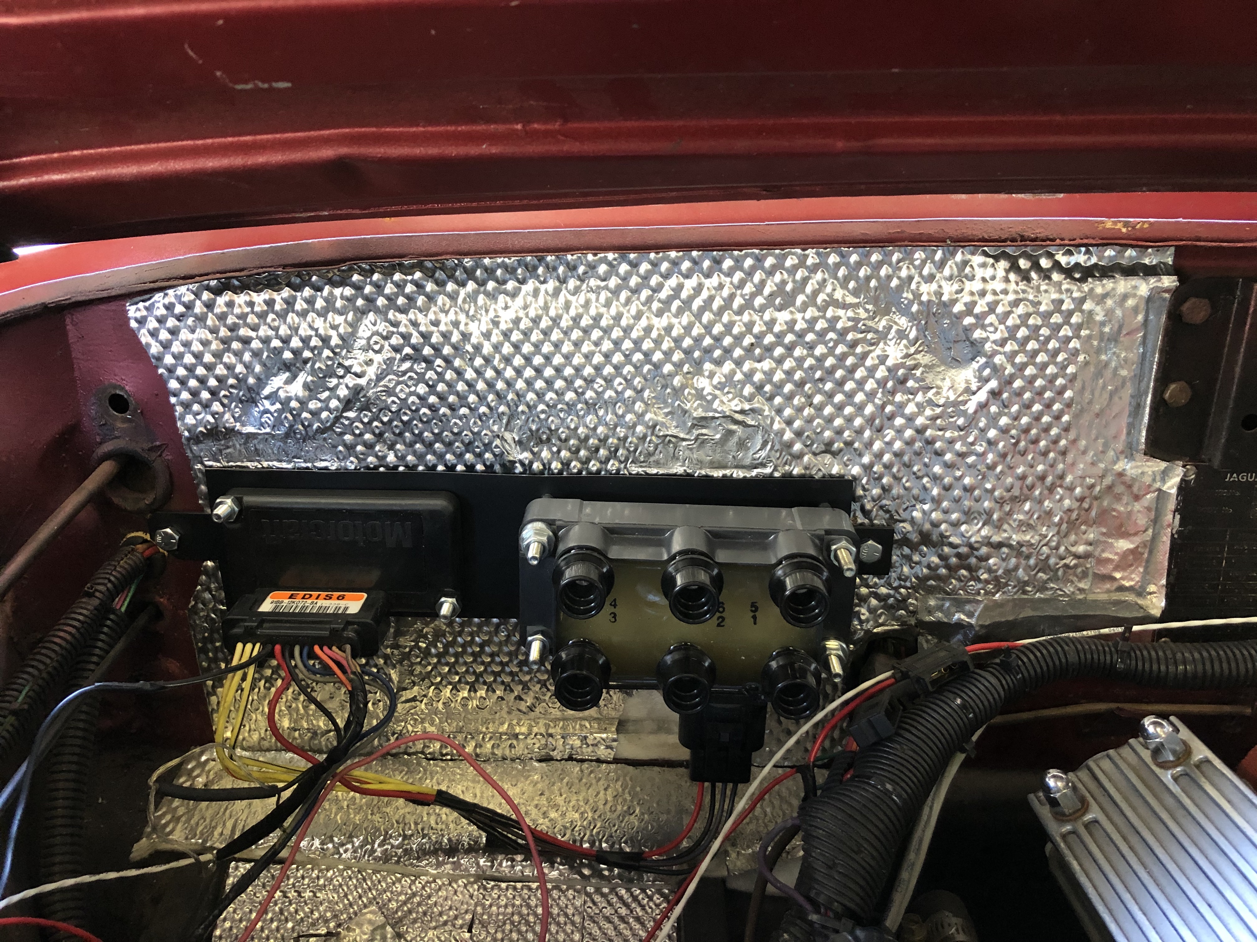
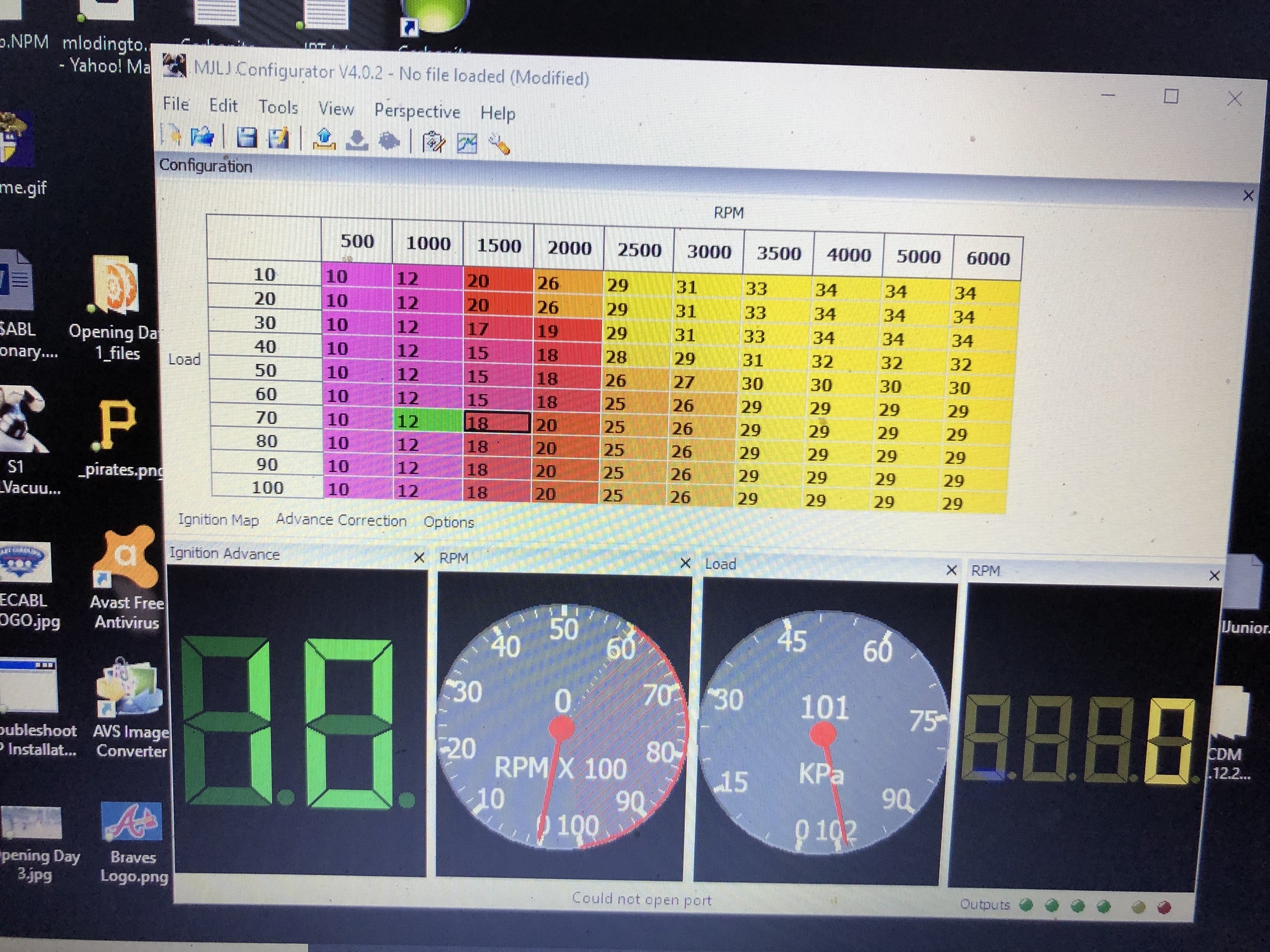
The technology is well documented in many places, but the core idea is a toothed wheel spins on the crank which is read by a sensor, that sensor tells a module and ECU the position of the crank. The ECU has an ignition curve programmed in it and tells the module when to fire the coil. The coil is actually 3 coils, one for every two cylinders (it’s wasted spark). The benefits are no distributor, so more accurate timing, and because there’s an ECU and multiple coil it’s a more modern timing curve and powerful spark. This conversion is well documented on the UK forum where Ray L used to sell his kits. He also has posted a bunch of different timing curves to download and try from other users who have had their cars dyno tuned with EDIS. Pretty cool reference and I would not have done this without it!
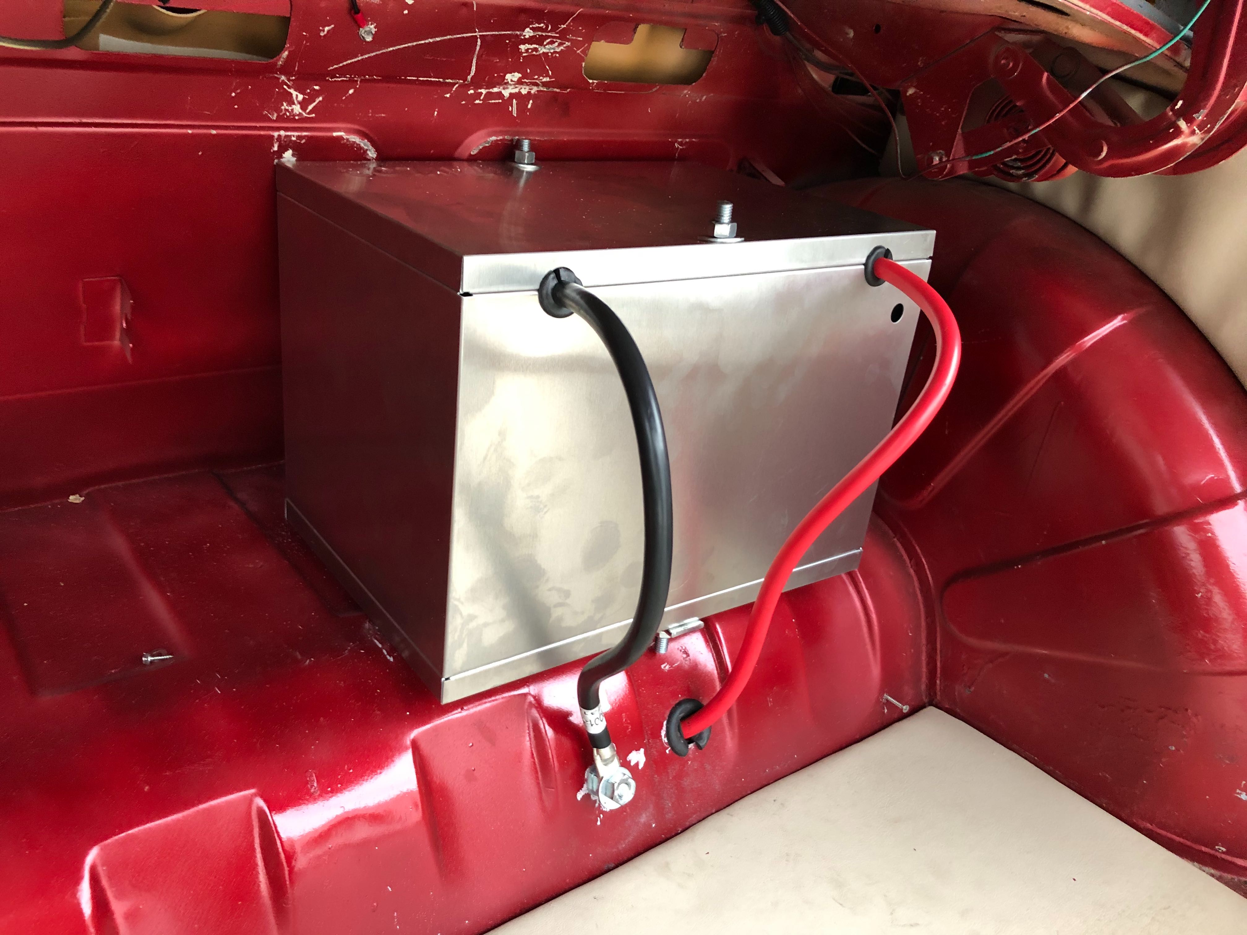
Most people hide the EDIS components, but I like to show things off a bit. My idea is to mount the kit on the firewall. This means, the battery has to go to the trunk. I got a kit from Summit that came with the box, battery cable, etc. I also replaced my battery as it was over 3 years old and with the large box I could get a bigger battery. I actually did this months ago and have noticed only easier starting with the larger battery, no side effects (also better weight distribution!).
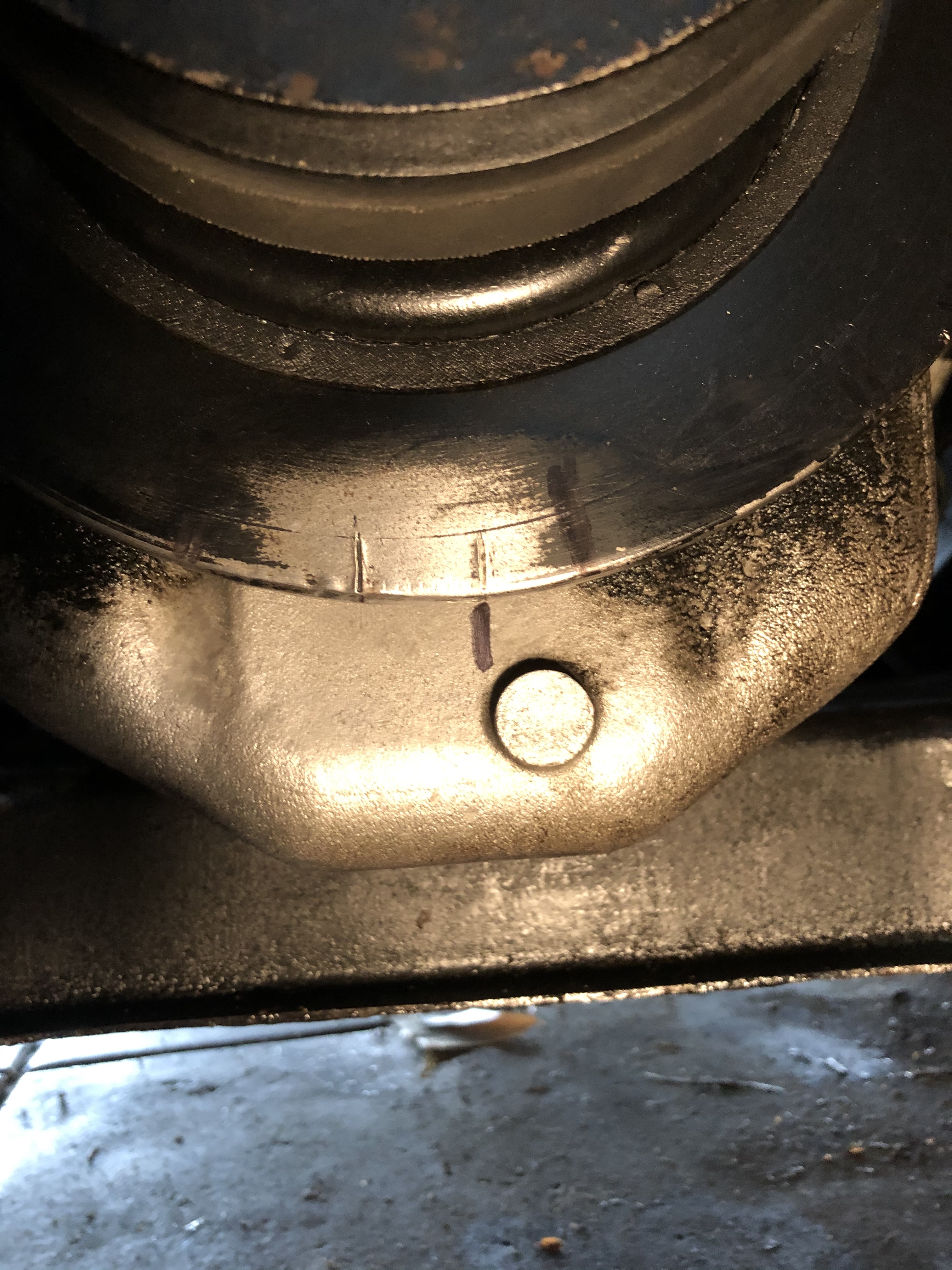
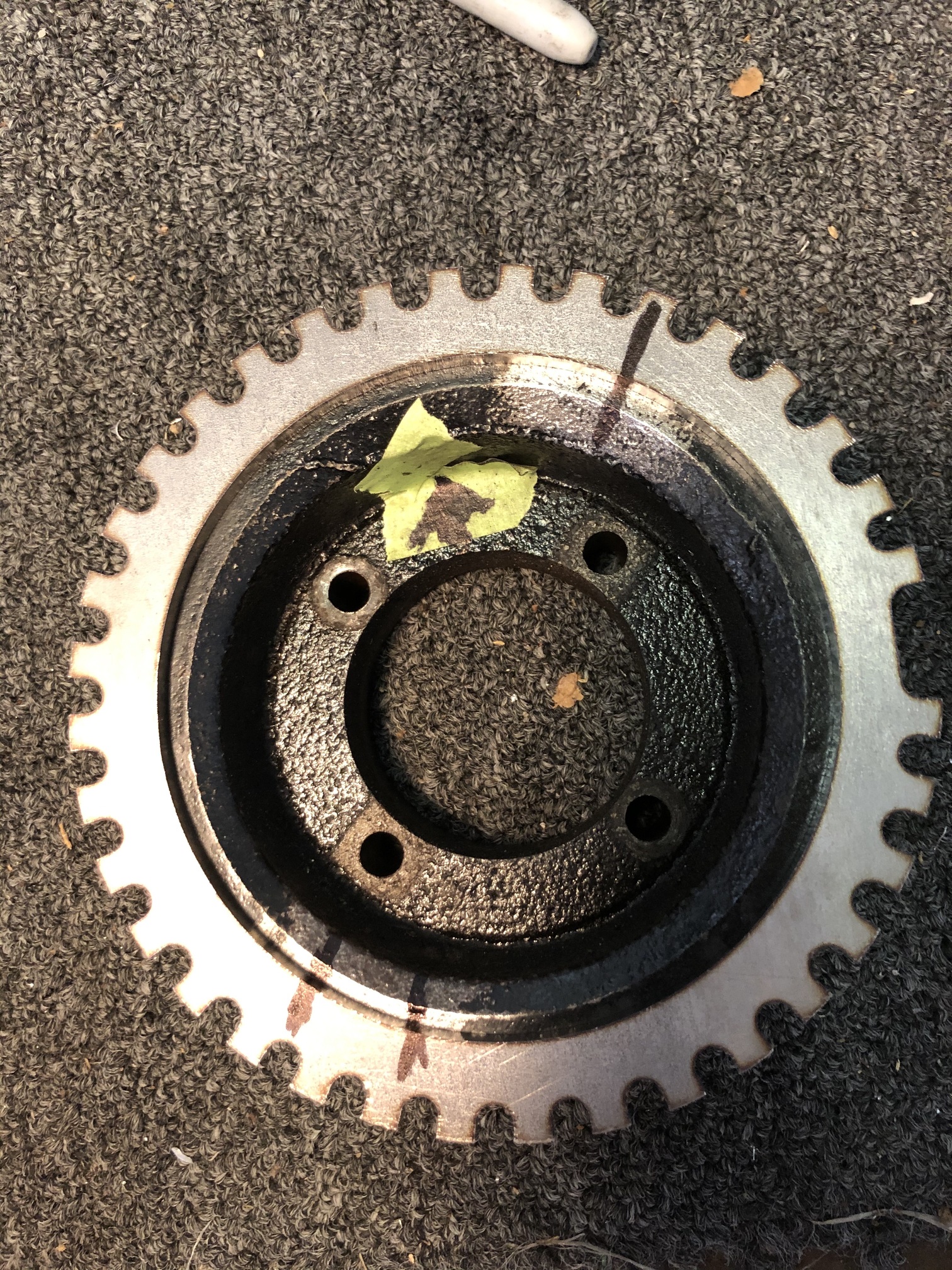
Next is to strip the front of the engine, and find TDC. One of the most important parts of the install is making sure the sensor and toothed wheel are paired at exactly TDC, otherwise the ECU will be off. This can be corrected by the computer a few degrees, but the mechanical install needs to be as close as possible. As you can see here, my timing point is at 2 oclock and paired with a slopped line of white paint. There are official notches on the bottom of the damper, but no marker. So I got some soft steel rod, rounded the bottom, and stuck in cyl 6 to find true TDC.

The method I found to give me the most confidence was, I made a sharpie mark on the oil pan in the exact middle, then used that to assess the notch on the damper. Turning the engine over and over, watching the rod stop at the top and go back down, I kept adjusting the sharpie mark until it was right in the middle of the highest point. Then made the mark in paint so it’s clear.
With that done, time to make a sensor bracket. This needs to hold the sensor within 1mm of the toothed wheel, at the perfect angle to read the spinning crank. I use 1/4" thick steel plate, with a 1" steel tube as the stand off. Here’s the piece that bolts to the timing cover.

Then I measured how long the tube needs to be, cut it to length, and made the second piece which will hold the sensor. I vice gripped the ring gear to the crank pulley to get the spacing and distancing right.

The sensor is mounted in a separate piece of steel, so I could move it around to the perfect spot. It’s also made in a way that I can use washers to get the gap between the sensor and wheel perfect. One big difference between my install and Ray’s kit was his uses a bold on wheel thats cut to be perfectly centered on the 4 bolts. You use extra long bolts with spacers to hold the wheel onto the crank and the crank onto the damper. I didn’t have the tools to make that wheel, so I thought I’d try using a ring type wheel, which I’ll weld onto the pulley.

 ).
).