Rob and Lee,
My main concern was the fiber washers if they needed to be between the threaded piece and the fuel pump. If not needed, I will use the threaded piece the way it is.
Not having done this work before I can make errors. It is best to discuss the situation to get a workable consensus. I will proceed with the fuel line installation.
Your main concern should be making the right bends in the tube to get the tapered end fittings started into the pump perfectly straight.
Once the threaded fittings are mostly almost tight, you can make further adjustments in the tubing bends to bring it in close to the chassis.
The new fuel system is in up to the engine bay. I now wish to wire up the fuel pump. I have a positive ground vehicle. When I brought the Jag home there was no fuel pump. Instead there was an after market electric fuel pump in the engine compartment.
Does someone have a wiring diagram book that explains how the fuel pump is wired and can you share with me that information, please?
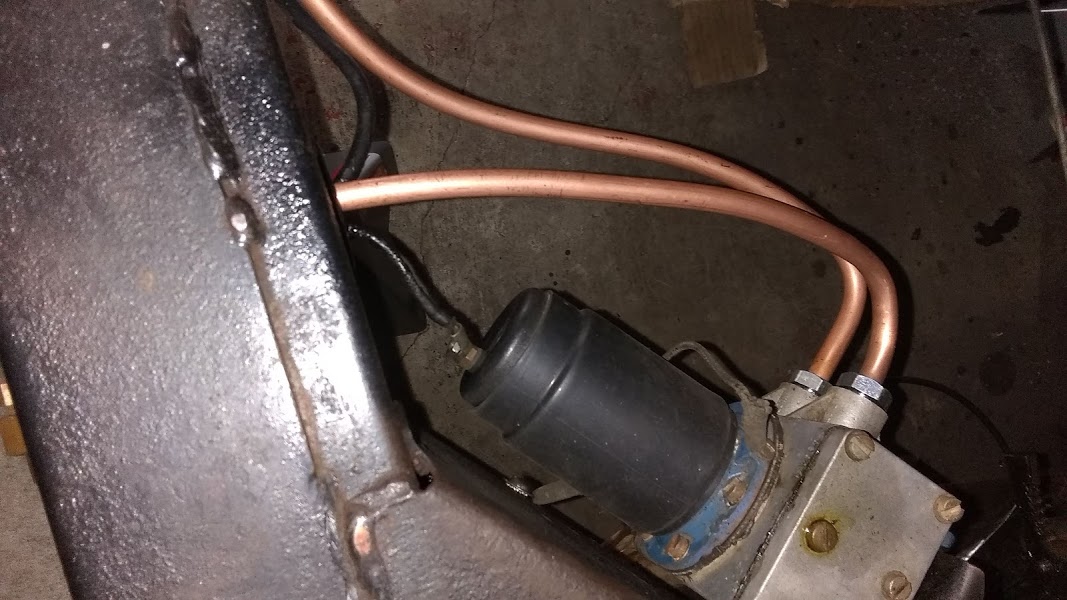
There should be, or was originally, a white wire from terminal A3 on the voltage regulator, running from there to the wiper motor area, with a bullet connection there to a white wire running down inside the stiffening channel welded to the scuttle (firewall) just outboard of the starter solenoid. This white wire continues through (inside) the chassis rail to the fuel pump (with black shrink tubing on the end) and is connected to the terminal on the cover. There is a black ground wire on the pump body, connected to the chassis.
Wellllll, I have a wire from the previous electric fuel pump which goes to the firewall hole passing into the cab. I have to assume at the moment that it ends up at the ignition switch.
There is a metal vacuum tube, I think it is perhaps the original temperature gauge line. There is an aftermarket one installed.
I think I am going to need a wiring schematic to sort this wiring out. It may be worth the money spent.
Maddy;
Send me your e-address as well as the “Production Year” and model of your XK… I’ll scan you
some relevant pages of a decent wire diagram… (in colour, even!!)
Charles #677556.
Maddy;
Yup… Got it, scanned ALL the pages… expect 9000+Kb in your e-mail inbox…
I suggest you simply print-out EACH page, in colour (except the last page.
it’s just B&W… That way, you will have your own personal copy of a rather detailed
XK120 Wire Diagram… I feel it is Very Easy to Read!! (better than the 120 SM!)
Charles #677556
I’d just like to add a couple of comments to this discussion about the fuel level sender, more to underline some of the points already made than to add anything new.
As in your case Maddy, my new 120 tank was painted on the outside, coated on the inside and electrically isolated from the chassis. So I added a new grounding wire from the top of one of the screws on the sender cover to a new local connection on the chassis. But then I discovered that the tank was actually grounded anyway through the copper fuel line, and the sender to the tank through its mounting screws.
The bigger problem came later when I was getting ready for a long drive. I filled the tank to a higher than normal level- I could see fuel in the bottom of the filler neck- and the next morning I found the car sitting in what had to be a several gallon puddle of gas on the garage floor. Not good. As Rob as pointed out so well, the cavity in the sender body is not sealed from the tank and it will fill up when the tank is very full. So it’s essential to seal the top plate on the sender and also the electrical connection terminal to keep that fuel from leaking out- which is what I didn’t do.
I will observe your cautionary statement Bruce. It is my belief that I did seal the sender gasket and since I don’t immediately recall, I’ll be checking that I did.
On another matter Charles sent me a wiring diagram for the ‘52 XK120FHC and when studying the involved connections I see that there is a white wire from ignition and fuel pump to the coil. I would like to inquire as to what gauge that may be. Perhaps a 14 or an 18 gauge wire? If I am going to run a new wire from the fuel pump would it not be advisable to use the same color wire as the diagram?
Maddy;
ALWAYS use the Same Colour Code AND the Same Gauge (diameter) of wire…
Changing either is guaranteed to melt-down your electrical system (One because some
idiot will put the “different colour” wire where the wire diagram says, and, Two too light a gauge
can melt/short out, too heavy a gauge will carry MORE amps than is needed at the terminus
which could result in the destruction of a VERY expensive part… OR CAR!!
Charles #677556.
The wiring on this car was done by someone who did not read the wiring for dummies booklet. It is quite obvious to me that it wasn’t done right.
The white wire from the fuel pump goes to the control box A3. Perhaps the original wire is still at A3 however no wire looks white even after cleaning it.
There is also a white wire from the ignition switch to A3 which I want to give that a look. I do not see how the wooden facia is removed to access wires behind. There is no access to behind the instrument panel from underside (above the floor panel).
If I wanted to purchase wire to replace the red one that is there I would need to know the gauge before purchasing.
Maddy;
Now is a helluva time to ask, but do you have an OHM Meter? It can be used to “trace” wires to insure the are (1) Connected, (2) Go where they are suppose to, and (3) nothing is “connected” that shouldn’t be or vice-versa. This is especially helpful where a wire leaves Point A and disappears into a covered harness… Other than it’s terminus point, one does NOT really know where the wire “goes”!! Checking continuity on “surrounding” wires might locate an odd “continuity”, thus giving evidence of a “short” somewhere between “Point A” and “Point B”!
I still cannot help you on the “Gauge” your wires are suppose to be… I can only suggest that you might be able to obtain a tool that will measure the gauge of a wire… That way, at least, an incorrect gauge can be determined or ruled out (assuming there is a “list” somewhere that gives the proper gauge for each wire…I know not of such!)
The Wire Diagrams I sent you ONLY show where a wire connects on “each end”… It does NOT show what harness/loom that wire is actually “in”!!
On the “colour” of “a”/“the” wire… Sad to say, the “colorfast” of Jaguar wiring sucked, at best… IF your XK’s wires are “original”, I’d venture an 90% chance that they are NO LONGER the original colour… NOT from someone changing them, but from age, chemicals, gas, oil, etc. causing some serious discolouration.
In many cases, on our XK’s wiring, installing NEW Wire Harnesses can be the best course of action. In fact, the wiring on my DHC was so bad (faded, tattered, etc.) I opted to simply buy all new harnesses for the entire car… the ONLY “wire loom” that retained it’s colour was the Manette Control (horn) wire harness, as it was protected inside the steering column… Now the kicker, the colours for the Manette Control were TOTALLY incorrect for an XK120… Yet perfectly correct for a MKVII Saloon!! Either the Jag dealership or the previous owner changed that harness out sometime before May 1967, when I became the second owner…
Oh, on removing the Facia… assuming you have an FHC or a DHC, the “center” wood panel is “attached” to the dash (metal) via four Hex Bolts (about 1/4"dia… two on each “side”, on the back side!!) it’s probable they are “BSF” (British Standard Fine)… If so, “American” (SAE) tools might not fit correctly!! Getting one’s hand up behind the Jag’s “dash” is, to put it bluntly, A Bitch!! IF you remove it and NOT get at least a half dozen “bandagable” cuts, you did good!!
Charles #677556.
Charles,
Thank you for your response. Yes I have a meter and I know how to use it. I had to do some electrical sleuthing on my Silver Cloud III.
A3 is where the white wire originates when going to the fuel pump. I do not know if any wire from A3 actually goes to the fuel pump as there is no wire coming from a fuel pump nor was there an original fuel pump. There was an aftermarket electrical one mounted on the rail in the i]engine compartment. I will figure it out. Thanks fir the warning on getting into the wires behind the dash.
It will be pretty difficult to address instrument panel wiring issues unless you drop the instrument panel to a horizontal position. To do this, you will need to lay on your back with your head under the instrument panel so you can reach up and remove the four nuts which hold the instrument panel in place.
Then you will need to reach up and unscrew the drive cables from the tach and speedometer. Then unscrew the oil pipe from the oil pressure gauge. Now you can begin to pull the instrument panel towards the rear of the car.
At this point, you will probably need to reach in from the top with a short handle slotted screwdriver and remove the two screws holding the oil pressure/water temp gauge in place, as there may not be enough tubing to allow the instrument panel to be dropped to a horizontal position.
I use a small table to support the instrument panel while I service the wiring, instruments, switches, etc.
Obviously, this is a difficult operation, so you will want to fix everything that needs attention while you are in there. Make sure you have plenty of good light and take your time. My car still has the original wiring harness, which has been repaired several times over the years with 14 gauge automobile wiring. Seems to work fine.
I’ve found the original terminal wiring ends to be problematic with their hardened black insulation that tends to crumble away. I typically clip off the original terminal ends and replace them with modern crimp-on terminal ends and shrink wrap insulation.
That looks very daunting! I am hoping that I do not need to get into that part of the car. Yet I choose to be prepared in the event I need to. Your picture speaks volumes in addition to your explanation of the process.
Thank you for posting this, I am taking a few days for appointments while I study what needs to be done. Thanks again.
On further examination today, I found the wire that comes from the control box. It is very brittle! It goes to the group of bullet connectors on the bulkhead on the right side. I attempted to wiggle the bullet connector which just disintegrated.
I hope to unscrew the bracket and mend that wire for the fuel pump then return the wires in that bracket but I think any movement will just cause the plastic to disintegrate.