I could use some suggestions on what you all have done to position the coil and routing of the spark plug wires. Comments are welcome but feel free to show off your work with pictures. I am also interested in where to obtain the parts/pieces.
Thanks to all I am truly grateful for the forum and the folks who share their accomplishments with their cars.
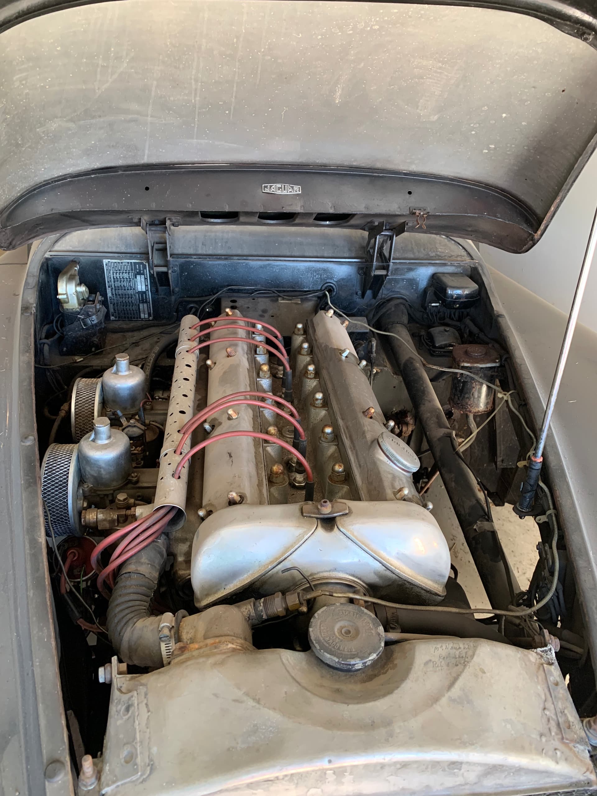
Below is an image of how my engine appears now. What would you do differently?
Maddy
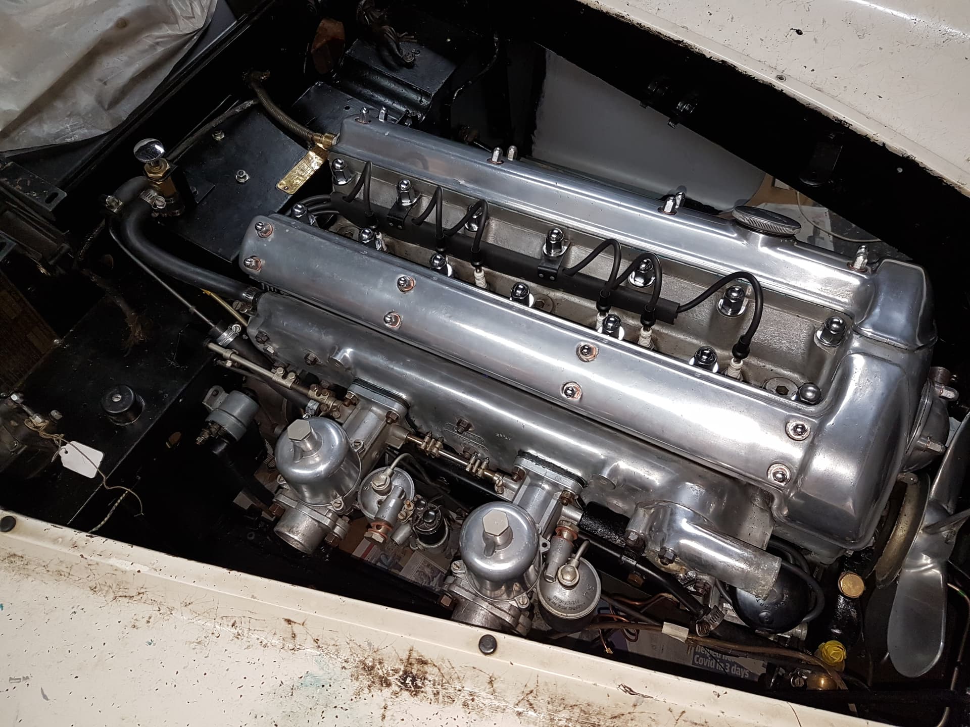
Rob’s photos show a typical set up. Some prefer to route the spark plug wires over the front of the engine, but I prefer Rob’s setup as it doesn’t obscure the front of the head and cam covers. Maddy’s metal conduit is not correct. The proper style conduits, as in Rob’s photos, are readily available in red or black from the usual vendors. My understanding is the red and black were used interchangeably during the XK years so either one is correct. I stand open to correction, but I believe the mounting brackets on Rob’s are for a later engine with lift pieces mounted at head bolts 2 and 6 counting from the front; consequently, the conduit tabs are at head bolts 3 and 5. The earlier style conduits had the conduit tabs at head bolts 3 and 6. I believe both are now available. Below is a photo of my XK 140 which shows the red conduit and the earlier mounting bracket locations.
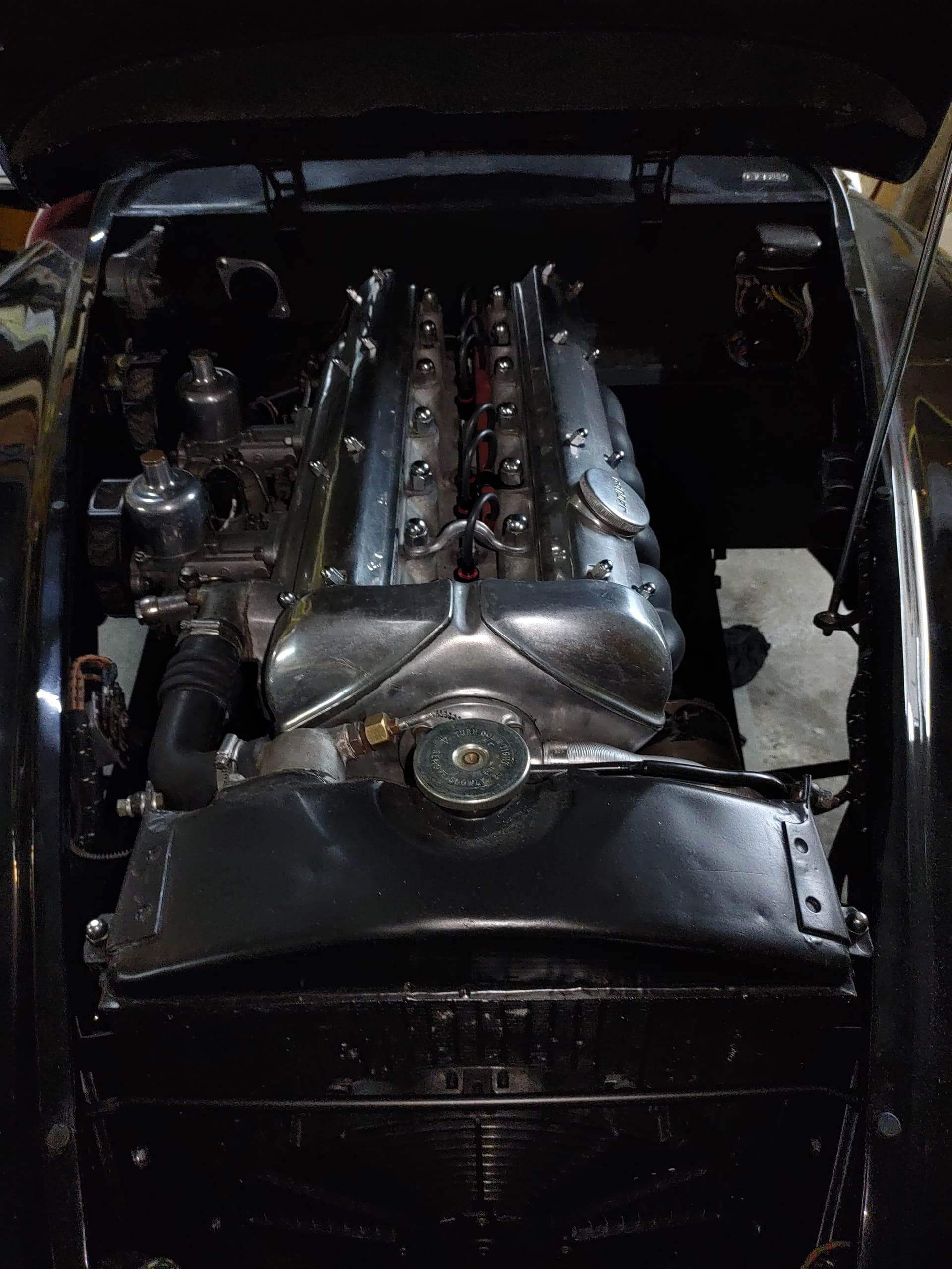
The routing of the ignition leads and the position of the coil mainly depends on how old you car is. The setup on my pictures is typical for a early steel body, May 1950 in this case.
Your cars engine also has no studs in the front part of the timing covers thus assuming an early model and most probably the same routing around the rear end of the engine.
My engine looks pretty close to Rob’s in appearance (as shown in your other post, Maddy). Your radiator looks to be in pretty good shape, the header tanks often get very dented over the years. Your air cleaners are obviously aftermarket, and the spark plug lead conduit is a home-made affair, by the looks of it. Someone has done what was a common period modification by putting a bracket between the front of the cam covers in an attempt to cure oil leakage which was a persistent problem with the early “studless” cam covers. The downside is that it was necessary to drill and tap a hole in the head itself, which can easily be welded up. You could even repair it with JB Weld, or similar, to make an almost invisible repair with a little bit of silver paint applied to it. The water temperature tube is routed down the wrong side of the engine bay, and the “JAGUAR” badge on the underside of the bonnet is not original - looks to be one from a hubcap. Oh, I’ve just noticed there appears to be no plumbing for the heater (on/off tap, hoses, etc) on the raised section behind the engine on the bulkhead (firewall), though I can see the holes.
Maddy, as long as you’re soliciting ideas for your Christmas list, here’s a few of mine:
Ditch the pink spark plug wires. Go with black copper core wire, which you can buy in bulk for very little money.
Purchase the correct spark plug terminals as shown in Rob Reilly’s photo.
Purchase a correct top radiator hose. Many of those sold by the catalogs have an incorrect bend point and look bad. @Clifford on this list periodically has the correct top hose duplicated and offers them for sale at a reasonable price.
Trade-in the generic hardware store hose clamps for the unique hose clamps (clips) admirers expect to see in an XK engine compartment. Early cars such as yours would been provided from the factory with TEX clips. Slightly later cars would have been provided with Cheney clips. (You’ll be forgiven if you purchase the far more common Cheney’s because good TEX clips are now quite rare and expensive.)
Eliminate the coolant overflow container. If one is actually needed, there are much nicer ones available. But it’s quite likely no overflow container will be needed if the radiator is in good shape.
Keep the radiator cap. That appears to be an original. Many XK120 owners would trade a kidney for it.
Maddy,
You’re getting lots of good input but it would help to know if you are looking to make the car “generally XK120 correct” or “authentic” for its model, year and engine number. If “authentic”, then please include the original engine #. As noted, there were two basic ignition harness configurations which changed at engine #W. 6697.
Unfortunately, (as in this case) sometimes “authentic” can actually mean “less serviceable” and “authenticity” becomes less important.
Good luck.
Ha, ha, and that is exactly why my early car which was originally like Lukas’s has the later plug wire routing and coil mounting. I burned my arm on a hot manifold trying to change a block mounted coil one night in a McDonalds parking lot.
The change in wire routing was at engine W6697.
The clamp across the two “studless” cam covers before engine W4691 was very common before the advent of silicone gasket sealants. Remember Indian Head gasket glue, it’s about all there was in the '50s? I’ve seen the clamp on Mark VIIs as well before engine A6959, when they added 3 studs. The timing chain throws up a lot of oil there. On mine W3962 Permatex Gasket Maker has worked very well.
Guys,
I prefer authenticity but will also modify if Jaguar opted to improve performance or personal injury is prevalent. The latter is a change for today since most owners do their own servicing.
That said, I like the suggestions so far and am considering the options. My main goal is to get the car started and do any cosmetic upgrades while doing this task. There are a thousand more things that need to be done on the car yet and that will come later.
For those who monitor modifications based upon year and engine number here are those facts on my XK.
20 March of 1952
Chassis: 679526
Engine number: W \4509-8
Gearbox: KL9837
In the photo above there are two arrows. The arrow at the bottom of the photo is where the rotor is pointing after setting the engine at TDC compression stroke.
The arrow to the top right is pointing to the distributor tower which is where the original #6 spark plug wiring is inserted.
The firing order is 1-5-3-6-2-4 from the bulkhead to the radiator. The rotor moves in a ccw direction. If #6 cylinder is the top right arrow the firing order would make the rotor pointing to the tower for the #3 cylinder. This seems wrong to me.
When replacing the spark plug wires, the distributor tower in the picture where the rotor is pointing ought to be for cylinder number 1. The next tower (ccw) should be #5, the next tower #3 and so on. I just want to be sure I have my thinking cap on correctly for when I replace the wires they all go in the proper towers from the spark plugs.
Your posting is valuable and having read the manual on this and accompanying information from Nick, I have all set up as indicated within your post. The wire placement from each cylinder into the distributor cap is my question. If the rotor turns counter-clockwise and the wire for #1 cylinder is located at the back side of the distributor cap, closest to the bulkhead, the next tower on the distributor would be cylinder #5 then 3, 6, 2, 4. In my picture the #1 cylinder wire should be in the tower - 2 positions in the counter-clockwise direction not where I have indicated on my picture at the arrow at top right.
I can only ascertain from my photo, the wires are in the wrong towers of the distributor and when running new wires all need to be positioned in the distributor cap as indicated in the image of your post.
If my thinking is correct I shall proceed with the replacement of the spark plug wires.
That sounds right. Of course it’s difficult to guess what was going on with the PO, but one guess is that the distributor was turned with the vacuum advance pointing to the block, i.e. 60 degrees from where mine is shown with the vacuum advance more or less parallel with the block, and the PO placed his wires accordingly.
A photo from a few days ago seems to show that your distributor is oriented (in relation to the engine block) the same as Rob Reilly’s distributor and the same as my disttibutor.
On your photo from today, you state that the heavy white arrow at the bottom points to the location of the rotor when the engine is at TDC and ready to fire spark plug #6 at the front of the engine. This is the same place in my distributor for firing spark plug #6 at the front of the engine.
I would double check that the engine is really at TDC and ready to fire #6. Don’t forget that the distributor turns half the speed of the crankshaft, and it’s possible for the TDC arrows at the flywheel to be aligned with the distributor not ready to fire #6.
When you are sure you’re at TDC and ready to fire #6, then mark the #6 tower on the distributor cap with tape. From #6 on the distributor cap proceed counter clockwise in the following order: 2-4-1-5-3.
Mike,
I have it set in my mind to double check the compression on #1 cylinder before The spark plugs are in. By hand I cannot turn the engine fast enough to do the compression verification. I have a little way to go before that can be attempted.
I am glad you brought that up. It serves as a reminder of the small steps that need to be done that are important to accomplish before the first firing.
A check for compression stroke…does not need a fast engine turn…in fact slow is better for accuracy of TDC…so if you think at tdc now…maybe as measured by a small stick in the #6 spark plug hole…by hand…then, roll car back just a little in 4th, or turn engine back just a little by hand at crank nut, so as to have the #6 piston on a little before TDC and on the rise, to next, with rubber stopper in #6 hole, roll forward in 4th, or turn at crank in proper direction, and to get the piston to be a little before TDC but on the rise—, (.with all spark plugs removed to make it easy to roll or turn) the rubber stopper in the front most hole (#6) will blow out as the piston rises on compression. If #6 is on exhaust tdc the exhaust valve will be open…and the stopper stays in place. If on compression…and stopper blows out…good…now…where does the rotor point …no matter where…(unless the distributor is not seated correctly) because who knows what changes may have been made thru time, One thing we know is…it is pointing at where the #6 spark plug wire should go in the distributor cap…Nick
Is that the proper conduit and mounting point for this configuration? It looks like the conduit is mounted backwards and on the wrong side with the usual mounting points for a 3.4 being head bolts 3 and 5 counting from the front. I don’t know the answer. I am just asking the question.