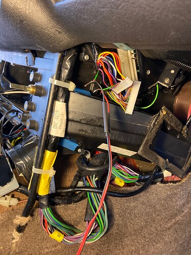
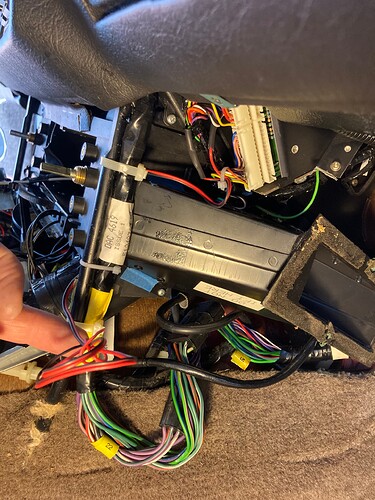
Had one of those in the 2000 XJ8 VandenPlas. But it was in the console, so cover down the console was an armrest. As I understood things, that phone was not compatible with the then current cell providers. I took it out and fashioned a new bottom for the interior of the console.
I had a “car phone” installed in my 88 Tbird. Very useful in my business…
A PO installed one in my 94 Jeep Grand Cherokee. Only the hand set is missing . MNIc on teh A post. Wiggly antenae oin the rear quarter window. box undder the passenger seat
Carried the Novatel bag phone equivalent, with battery pack, 89 to 96 - was well worth it back then - unfortunately became unusable with arrival of digital signals.
Had one back in the day also. My girlfriend at the time worked for AT&T in NJ were they were making them at the time. Had it hooked up in my 1982 BMW Barvaria, it was a big honking thing much bigger than yours. OMG 
Interesting, as my dad was also a gunsmith, and in fact he had originally hoped his tooling company would expand into an arms co., but that never happened. That’s fate I guess … 
Wasn’t there a business where you could stick a fake cell phone antennae on the roof to pretend your car had one and be a cool yuppie!
Buddy of mine had one of those. He called it “Cellular None.”
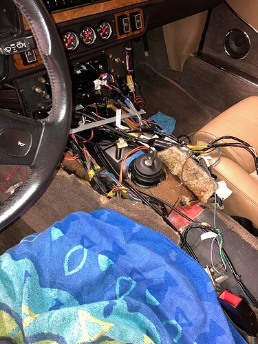
One more non-transmission update. Although these are things one might do when you have the ski slope or console out, such as you do with a tans swap. This is what I did this morning while waiting for FedEx to bring the transmission.
First, here is my power antenna switch setup. It just interrupts the power antenna wire. Since I don’t know which harness the wire is buried in I just tapped in behind the deck. I picked up the amp turn on wire, which I ran to the boot with the RCAs, on the “deck” side of this switch so the amps are unaffected. Direction is same as the window switches. Forward=Down.
Next, here is the basic Napoli mod from page 540 of the Book. This is a splice is the green/red wire from pin 20 of the Delanair mk3 control module, which controls the ac compressor relay. I have a nice push button which will go in the console so I can either let the system operate as normal with the CM turning on the compressor, or I can disconnect the compressor and just run the blowers. Note that the electrical diagram calls this a green only wire. The pin number matches and all adjoining wires are the correct colors, so I am pretty sure this is the one. I had a bit of fine gauge black and red wire that I used for the splice/extension.
FedEx showed up as scheduled and we have a transmission!
I took a few quick measurements and confirmed that the shifter will be about an inch behind where I thought. No problem. I will take half the blame. American Powertrain drawings reference the “face of the block” and the “tip of the input shaft” as being the same point. Obviously they are not. Their verbiage, however is correct. I was going off the drawings.
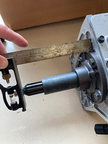
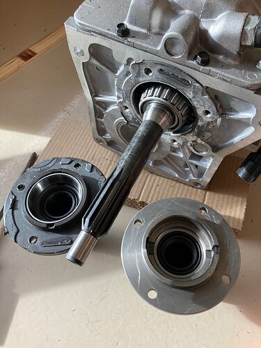
This is a quick check to make sure I am not going to bottom out the pilot bearing. But the point of the picture is that you can see the large step at the base of the front bearing retainer. The retainer that comes with the Ram throw out bearing has no such step. So that’s at least one difference.
I removed the bearing retainer and realized something else. The Ram unit does not have a bearing race installed. I spent about 30 minutes fretting over how I was gonna pull the race without damaging it. There no way to get under it. I was poking at it with my finger to see if there was any “lip” at all and it came right out. Oh yeah. It’s a slip fit. Because you put shims behind it to set up the preload. I knew that!
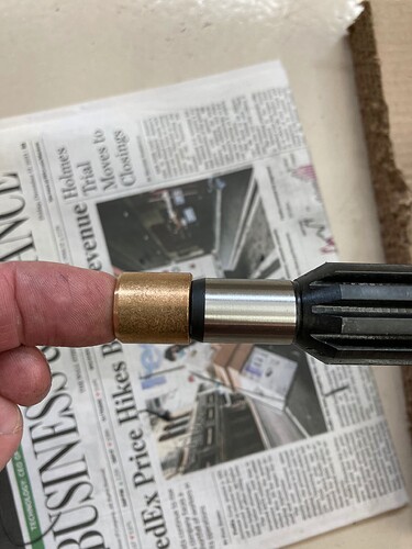
O.K. crisis averted. Next check is the pilot bearing. Uh oh. The input shaft tip is way bigger than I expected. It’s only about .080 smaller than the OD of the bearing. That won’t work. I will call American Powertrain tomorrow if they are open and see if I can get a different input shaft. They are easy to change, they just pull out. (But don’t drop the synchro rings into the bottom of the case…). This “Cobra spec” trans has a tapered roller bearing up inside the back end of the input shaft, which is easier to deal with than the needle bearing versions. (You are seeing the front bearing in the pics above, the bearing I am referring to is inside the case at the moment, between the input shaft and the main shaft.)
I will see what AP says but I am leaning towards just turning down the tip of the input shaft to the .500 diameter necessary to fit the jag pilot bearing. I hope/think the part is hardened all the way thru vs case hardened.
Moving on, since there is no pilot bearing or flywheel in the car at the moment it’s time for the good part. The bellhousing is on snug with a couple bolts, and I temporarily put the new bearing retainer on the trans.
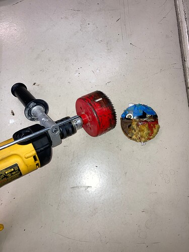
I tried installing the trans without a shifter hole but the tail shaft won’t come up high enough before the shifter hit. Not surprising. Time for Commitment with a capital C. I triple checked my measurements and got out my 4” hole saw. The new location is right at the seam of the tunnel cover and the tunnel. I masked everything off and went to work. I wanted to cut it dry so I would not have cutting oil in the car, so I went slow. One kind of cool thing was that the front half on the tunnel cover cut thru quickly and from then on about 80% of the chips dumped out under the car.
I thought I might have to oval the hole to get clearance to install. But nope! After a couple of tries (O.K. about 6) the trans slipped into place and the shifter cutout looks great.
Tomorrow I will temporarily snug everything up and set the output shaft height so I can measure for and order the driveline. Then I will start figuring the transmission mount.
It was a pretty good day 
What is being accomplished by operating the blowers independently? In and of itself the Napoli Mod is unclear as to it’s usefulness. However, if one were to implement both the Napoli Mod and the Gardner Mod together, that formula is very clear.
It’s that 80% of the time you don’t need the fans, the ram air is plenty enough once the car is moving.
I have done all the above mods and found them all to be very useful.
Hi Bob, Agreeing with Aristides post , I added three switches to my climate control, and one further mod.
Compressor shutoff is #1. Another switch which disables vacuum solenoid, allowing fresh air vents below windshield to stay open, encouraging airflow into cabin #2. A vacuum controlled switch which turns of A/C compressor when engine needs more power. (like ascending steep hill using cruise control) #3
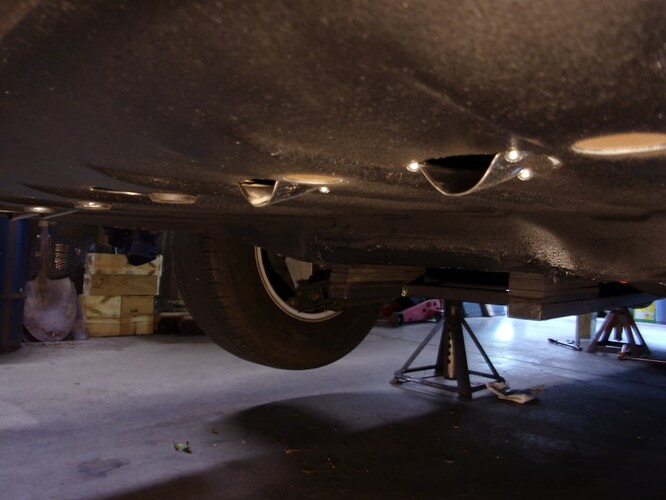
Finally, my car is a Cabriolet. There are no “B” pillar vents. Any “venting” is through floor of trunk. I experimented and added four marine clamshell vents, which greatly improved airflow at highway speeds. Put false floor in trunk so air from cabin could escape.
So you have two bearing retainers, one that came with the transmission and one that came with the throwout bearing? And the one that came with the throwout bearing is the one shown back in message #74 where you machined the OD? I presume both the bearing retainer swap and the input shaft swap mean you’re going to have to reshim that front bearing to spec?
Are you at all concerned that the heads of the bolts holding that bearing retainer to the transmission might overhang the OD and interfere with installation in the bellhousing?
Yes, yes and yes. Re: bolts, I was concerned but they did not, there was no overhang and the trans slipped in to the bell no problem.
The trans and bell are temporarily in the car now. I measured driveline and went down and ordered it this morning. Now I am figuring on the rear mount.
Flywheel and clutch still at the machine shop, expect to be done Monday.
Umm… you just dropped your front subframe! ![]() I am pretty sure you are well ahead of me as far as big winter projects!
I am pretty sure you are well ahead of me as far as big winter projects! ![]() . Great job btw!
. Great job btw!
Any benefit to a little Loctite to prevent this bearing race from walking around in the retainer?
Couldn’t hurt. I need to read up on setting the preload. I will see what Paul’s book says.
Yesterday and today were all about the transmission mount. I knew from the beginning I was going to have to fabricate something. In the interest of time, I decided to forgo the spring mount for now. I still think it’s possible to use it, and if I don’t like the way the car feels with the rubber mount, I may re-engineer things.
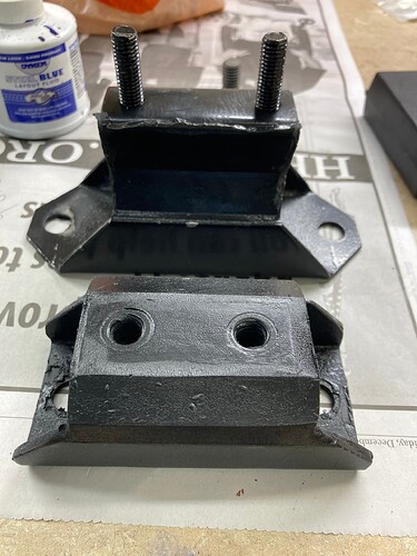
This is a stock mustang T5 mount, on top, and on bottom a stock GM TH 350 amount from a 1970 Camaro. PN Duralast 2378.
Initial mark ups indicated the T5 mount was going to be way too tall, I would end up with the crossmember hanging down too far. I needed a really low profile mount. The GM unit fits the bill and is available at any parts store.
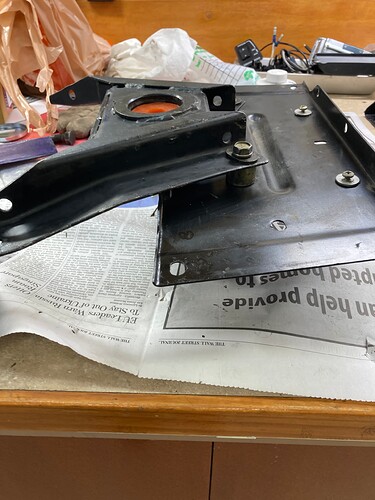
Here is everyone’s favorite XJS part, the stock crossmember with the spring mount set up. The front part of the crossmember assembly supports the spring, and the rear crossmember supports the back of the front crossmember. The spacers are factory.
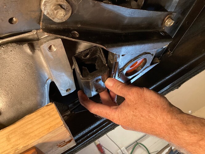
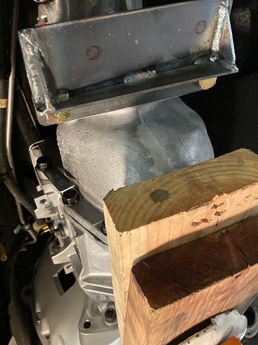
This is the cross member in the car, and you can see the mounting surface on the transmission. This is about where I want the new amount to be. It looks like there’s room, with a minimum of drama.
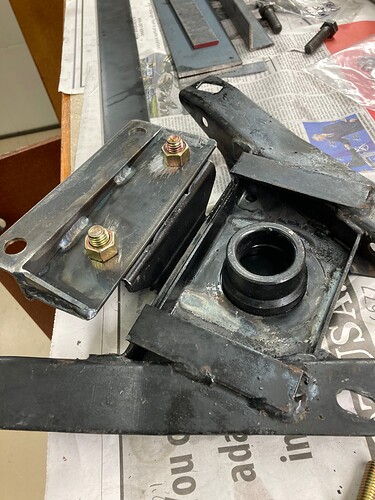
Of course nothing is ever easy, and just to make things interesting late model Ford T5s have a built-in oddity. When installed in the mustang the trans is rotated about 6° towards the driver. Apparently many Camaros do this as well, I’ve just never personally seen one. The rotation is at the bell housing/trans mating surface, and the rear mount mounting surface is built 6 degrees from level, so that when the transmission is rotated, the mounting surface is level. My bellhousing is for an earlier t5 where everything is square, which is what one would expect. it is difficult to notice this in the pictures above, but if you look close, you can see that the transmission mount surface is not square with the crossmember. So we’ll solve that issue as well. Here are the parts I cut for the solution I came up with.
I built this adapter that provides a new mating surface for the TH 350 mount, that is also level. You can really see the rotation in this pic.
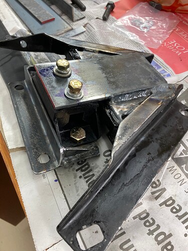
Here it is with the GM mount attached.
Next, an extender is welded to the factory crossmember.
Here is everything assembled on the bench.
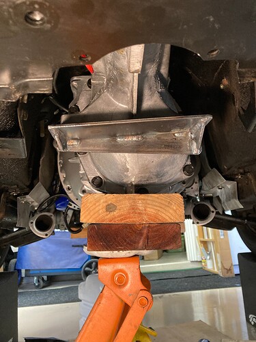
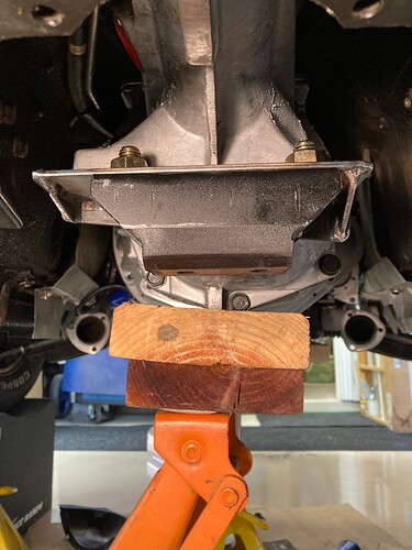
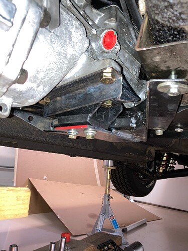
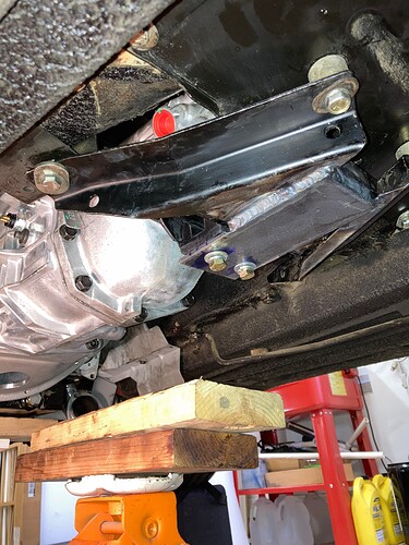
Here is everything in the car. I will need to fab some large diameter spacers, similar to the rears, about 7/16 thick, to go under the front mount points of the front crossmember. This will give me the correct tail shaft height. I think I will also replace the rear spacers with a solid bar, just to give a little more surface area for everything to clamp.
I still need to do final deburring and paint, but we’re looking pretty good at this point.
There are probably at least a dozen different ways to solve this, one would be a complete custom crossmember. I wanted to retain the factory crossmembers, I am not sure if they provide any real structural integrity, but who knows. With my luck I would take them out and have some sort of weird come and go vibration. And frankly, it was also just easier.
The factory crossmembers have slotted holes pretty much everywhere, and I drilled the holes in the new adapters a size larger than necessary, because these transmission mounts aren’t exactly precision units. This gives me a chance to align everything and clamp it down really good without any undue stress.
I’m going to sleep on it to make sure I didn’t forget anything, and then I think the next step is to pull the trans back out of the car and prepare for clutch fly wheel and pilot bearing install.
Very nice! Creative welding- I like that. Glad to see you didn’t use a Poly mount. I did when I changed my trans. mount and got annoying vibration. Back to rubber. You are making rapid progress!
One thing I forgot to mention, this clearance between in the back of the transmission and the crossmember is too tight. I’m not going to cut on the crossmember, so after I pull the trans out I will grind off a bit of this unused flange to give me a 3/8 inch or so. There’s daylight there, but once the rubber mount settles it would definitely touch.

