I first checked the coil connections to the metal part, and both show an open circuit
I checked the coil resistance, including with my multimeter in “diode” mode, and it’s the same with both polarities, so no diode in there
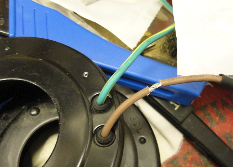
That looks green with a yellow stripe.
Australian wiring regulations for household appliances and similar things connected to AC require:
Earth - green/yellow.
Active - brown.
Neutral - blue.
I am fairly sure this is an international standard used in many countries.
That means 300V rated PVC wires in those colours are made in vast quantities and easy to find.
In this application the colours are not essential but do make sense.
Probably no diode in that item but wise to check.
I though of the same color coding, but the stripe is white (which makes no big difference in this case)
I tried t check the diode when I twas testing the loom, but couldn’t get a reading in diode mode : it may have burnt,
I’ll have another go at testing it, and may install one if I think it’s busted, as I’ll need to alter the wires anyway
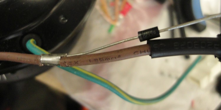
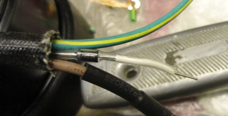
I started removing the black plastic tubing used for wiring protection on the new coil, and found a 1N4007 diode hidden in there., between the 2 wires.
The polarity of the diode confirms the initial guess :
brown is positive
green / white is ground
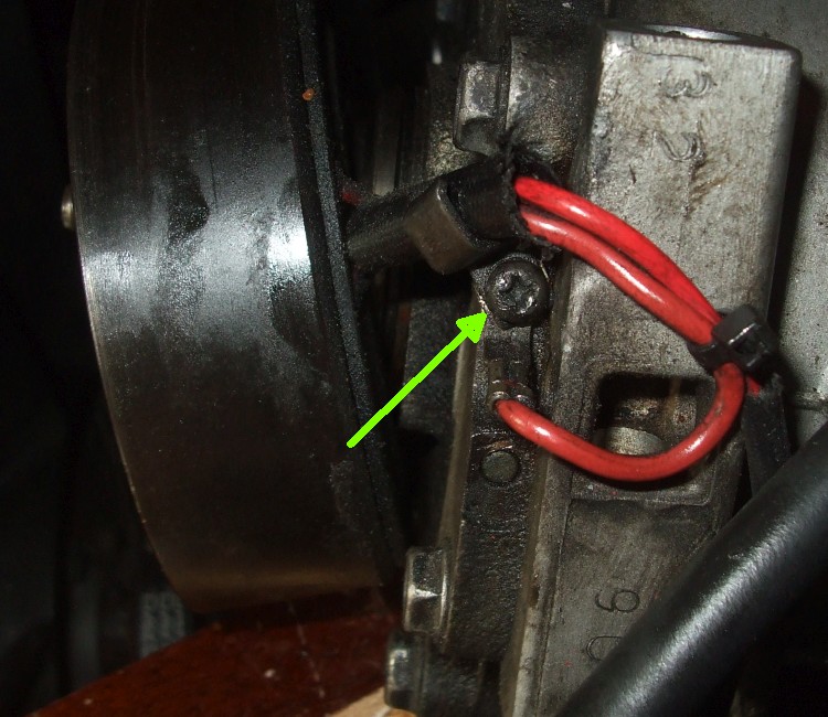
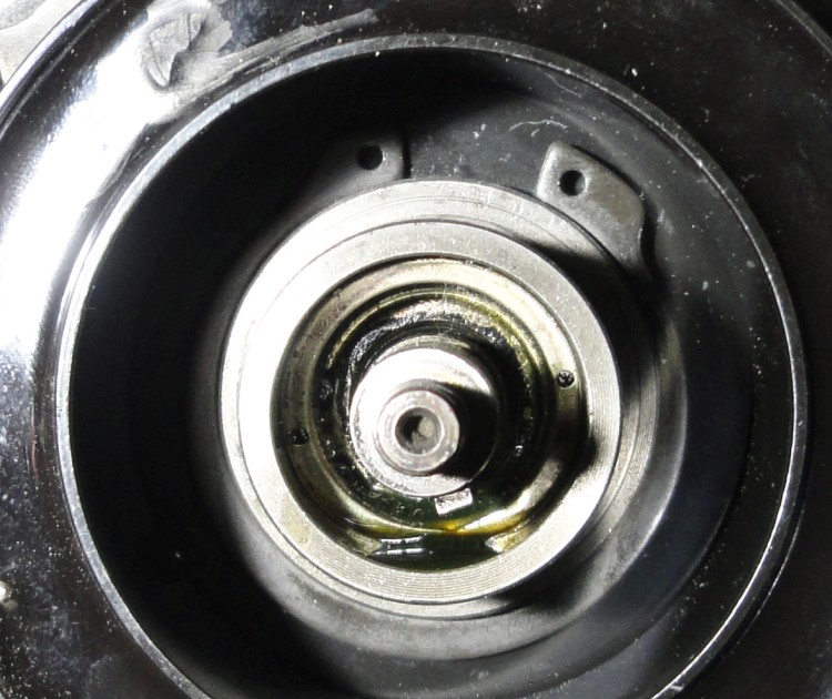
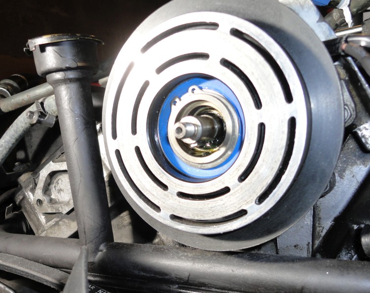
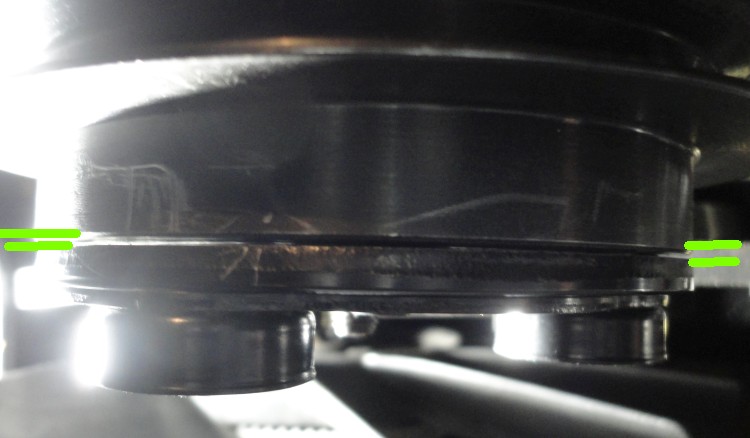
I wanted to check the coil positioning before deciding to reinsert a diode or not ; the fitting seems ok, but the small Philips screw holding the groung connector seems to be busted : I’ll need to find one as it desn’t seem to be a metric thread
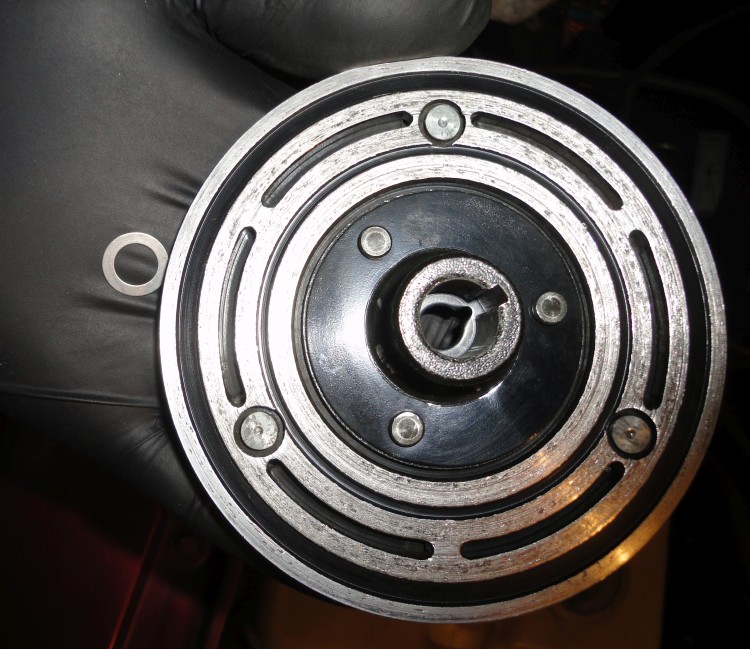
as posted above, I damaged the thread of ths Philips screw fixing the ground wire on the body of the compressor
it seems to be thinner than M4, so could be 8-32 UNC is there anyone who knows the size and thread of this screw, or who could measure it to confirm ?
thanks in adanbce
yes it’s a ground, but I’d rather reuse the same fixing point since I shortened the wire to match:tired_face:
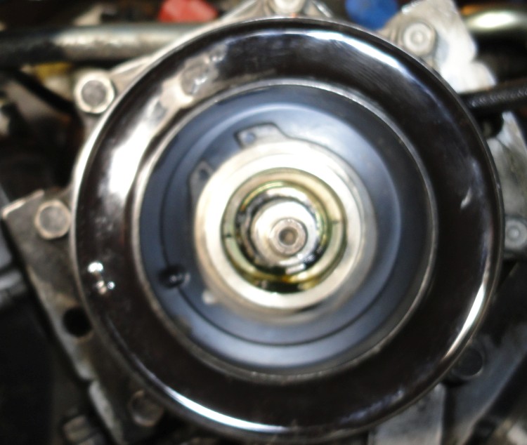
If needed I’ll pick up the ground on the fixing bolt (top right) rather than the hex head on the left, as this is one of the bolts holding the compressor front to the body
as posted earlier, I opened the plastic tubing covering the wires, and found a diode crimped on the wires , confirming that brown is +12V, green/white being ground
I was surprised to find it, as I couldnt detect it using my ohmmetre. I reckon the very low resistance of the coil makes impossible to locate the blocking polarity of the diode
I searched similar crimping terminal, in order to refit the diode on the shortened wires, as I have doubts about the on which should be in the loom : better 2 diodes in parallel than none.
Farnel provided the “open barrel crimp” I needed, so I started crimping the diode on the wires :
Did you remove the old diode ? It’s quite possible it’s shorted.
Yes, two in parallel is much better than one, they should have used a beefier one in the first place (that’s what I did).
If the coil is rated 2A, then it is around 6ohm and with a diode across it you could not identify the diode with a multimeter. If it was a short you could see it.
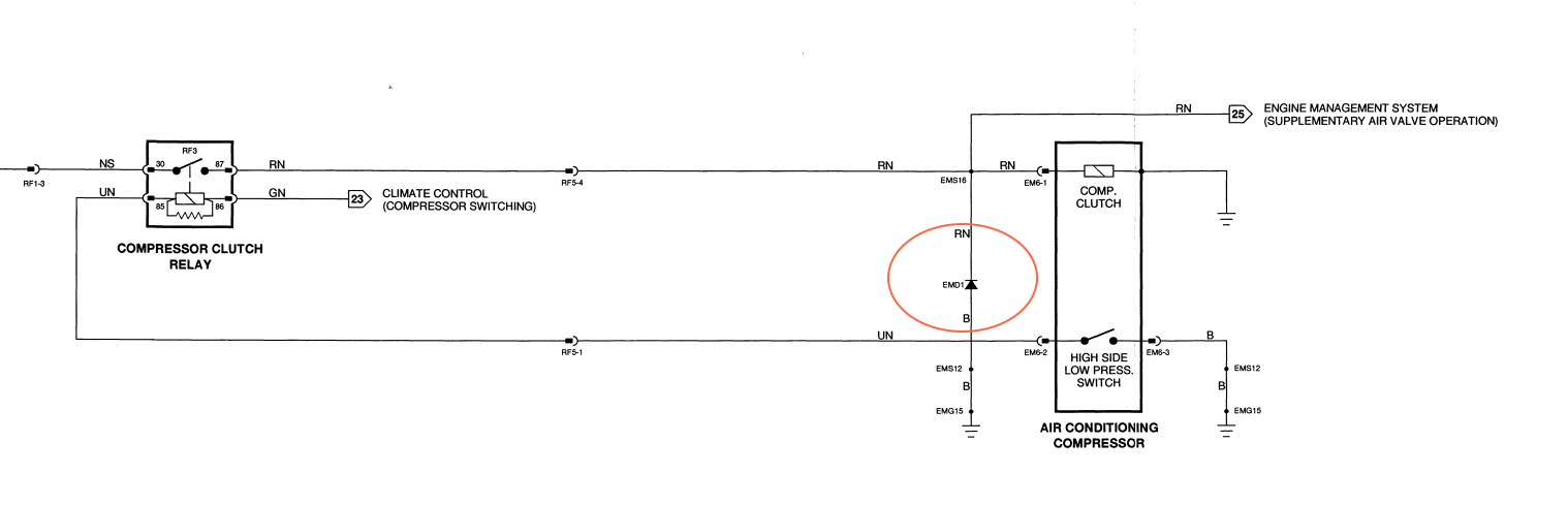
The diode is only there to stop the relay or FET or whatever drives the coil from seeing the inductive voltage spike as the coil switches off.
1N4007 is 1A rated and is fine, it will take a 2A spike easy enough.
You could use a 3A diode, I think maybe 1N504 or similar. It is a bigger package.
the coil by itself measures about 4 ohms, so 3.25 Amps on 13V
the 1N4007 was fitted on the new coil, but I didn’t realize before measuring the assembly that my ohmmetre was unable to sense the diode beacuse of the coil
I’ll have a try at checking the current one in the loom before reconnecting the new coil, just to know if it is still on or busted open
Kirbert
(Author of the Book, former owner of an '83 XJ-S H.E.)
53
If you connect the VOM one way, you should see 4 ohms. If you reverse the leads, you should see less than 1 ohm, correct? In fact, seeing different ohmage readings with the leads swapped would be enough to tell me the diode is good.
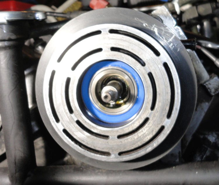
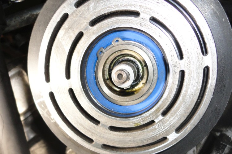
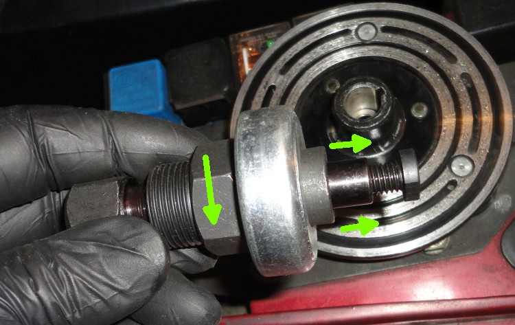
the special tool needed to push the plate on the axle :, by turning the big nut
(the screw on the right needs to be removed to screw the tool on the thread of the axle)
Better measure the diode directly.
One way it should be infinite, the other way around 170 kOhms for the 1N4007.
I would rather put a 1N504 to be sure as Richard suggested.
Very nice work on the compressor by the way, thanks for sharing!
Aristides
Kirbert
(Author of the Book, former owner of an '83 XJ-S H.E.)
57
170 KOhms? What good is that? It wouldn’t flow enough current to do anything!
Yes, it’s counter intuitive I know… diodes are weird beasts.
I just measured it with my multi-meter and that’s what it reads in the “resistance” setting.
Normally multi-meters have a special setting for measuring diodes and continuity, and in this case one way it reads 570 (correct polarity) and the other way 1 (reverse polarity).
It will never beep, i.e. will never show a short circuit.
The average multimeter when testing a diode should show many megohms in reverse polarity, probably off the scale in fact.
In the forward direction it should show some resistance and it can vary a lot. The apparent resistance is just the voltage applied divided by the current measured. A small difference in voltage across a diode can make a huge difference in current measured, that is characteristic of a diode.
I just tried a 1n4007 on one of the cheap multimeters around the house. That shows off the scale in both directions in 200 ohm to 200k ranges. Useless for a diode test. BUT it has a diode test facility. That shows 570 forward, off the scale in reverse. That works.