Adjusting Ride Height of XK 120

Need the help of some “clever” people or alternatively those with a lot of experience that “have been there before”.

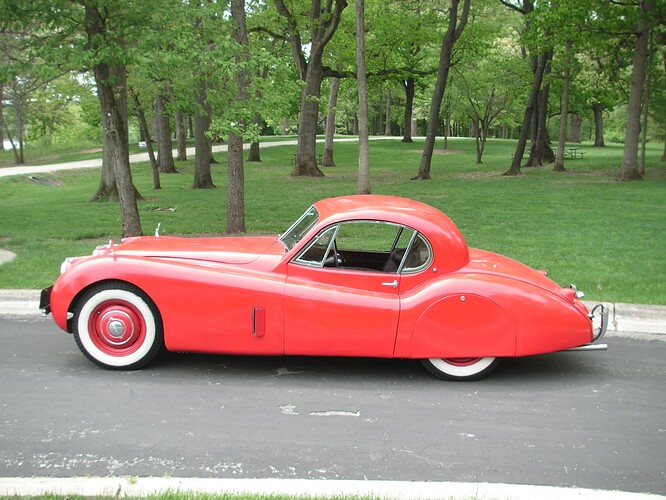
After 2 years of restoration, I had my 1954 XK 120 OTS on all four wheels today, now with engine and body on the chassis. It was immediately clear that the ride height at the front was too low. Measuring under the (beginning of the) straight part of the main chassis beams, I wrote down 6.25" where it should be 7 inches. So 3/4" too low.
No questions on the way the adjustment should be made, but this time the following question:

Does anybody know the relation between 1 turn of the brass Adjustment Nut C.3097 and the resulting increase/decrease of the ride height under the chassis?

I know that the most applied technique for this is “try and measure” but why not “first time right”?
I did some calculations (as I don’t have the experience that some of you might have in this area) and came up with the following. If you’re not interested I can fully understand and you can stop here.

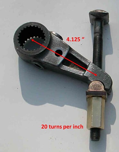
Adjustment bolt C.3096 has a UNF ½“ thread with 20 TPI corresponding with a distance of 1/20 (0.05) inch per full turn. There are 24 splines on the end of the Torsion Bar meaning each change of spline changes the position of the torsion bar by 15°. The distance from the heart of the adjusting bolt to the center of rotation of the Torsion Bar is about 4.25 inches (see pic below). Changing the position of the Adjustment Lever by one spline (15°) equals about 1.125 inch adjustment of the brass Adjusting Nut C.3097, which is equal to just over 22 turns of the brass nut. So if you turn the brass Nut C.3097 more than 20 turns, it would be recommended to change the position of the Adjustment Lever to the next tooth, in order to keep the position of the Adjustment Bolt more or less in the same spot.

At the front of the Torsion Bar, the length of the Lower Wishbone Lever measured from the center of the Torsion Bar to the center of the Wheel is about 17 ⅞”. So, any adjustment of the position of the Adjustment Lever via the brass Adjustment Nut has a multiplication factor of 4.3 (17⅞ divided by 4⅛) assuming the Torsion Bar is totally inflexible (which it is not).

This means that one turn of the brass Adjustment Nut C.3097 (representing 0.05“) will translate in (4,3 x 0.05” =) 0.215“ at the road wheel To compensate for the ¾ inch that the car was too low, I would need 3.5 full turns of the brass Adjustment Nut. (0.75 divided by 0.215” = 3.5)

Comments please or even better if somebody knows the relation between turning the brass nut and the increase/decrease of the ride height, please correct me

I will start tomorrow with the adjustment and hope to be able to tell you within a few days whether all the above is correct or simply bull …

Bob K.
1 Like

Your calculations are correct, and that’s the way I would have done it if I was working on the production line and did this job all day every day.

1 Like

You may be overthinking this one, Bob. It took me maybe 15 minutes to do the job, it’s not complicated. I used a 7” wide piece of plywood as a guage, raised the front of the car to take the moment off the torsion bars (otherwise you risk breaking the bolt), torqued down the nut, lowered the car then bounced the front end a bit, took another measurement, raised the front end again and so on. I had my wife sit in the driver’s seat and weighed down the passenger side and boot to approximate appropriate loading.

4 Likes

Hi Bob…great calculations…it all sounds correct. …would be a great way to dial in the ride height…waiting for your test results…hope it works out…was you 3/4 in too low after useing the reccomended setting link dimension tool…Steve

Steve,

Yes I used the special tool which apparently only provides a “starting position” for the adjustment. But (if my calculations are correct) the Adjusting Lever has been positioned in the right spline and we only need an adjustment of 3.5 turns (and there are 22 turns per spline). If you look at it like that, it was a good starting position and I don’t have to change the position of the Torsion Bar itself (always look at the bright side of life…).
The official Jaguar Workshop Manual mentions the use of the “simple distance gauge” but then continuous: “Test torsion bar settings and correct, if necessary, as described below”. So, also Jaguar had to conclude that the ride height was not always correct after the tool had been used.
I remember that I had to adjust the ride height of my XK 140 FHC as well, even though I also used the special setting tool.
Will let you know how correct the calculation was (hopefully later today).

Bob K.

1 Like

Keep in mind that a torsion bar like a spring has a raising rate factor whether it is compression (spring) or (twisting) torsion bar, you may find more turns of the adjusting nut will be required to achieve your desired ride height. That was one component not considered for your otherwise excellent calculation.

Bob did mention that his calculations were based on the torsion bars being inflexible which he knows they are not…Steve

I would have thought that the torsion bar spring rate would remain pretty much exactly constant, especially within the small range of torsion bar twist happening during these ride height adjustments.

1 Like

Did the “experiment” this afternoon, using the multiplication factor of 4.3 and turned the brass adjustment nuts with the calculated number of turns.
I obtained only about 25% of the assumed increase in ride height.

The only conclusion can be that:

  • the torsion bar is absorbing a lot of deformation before it actually starts to rotate
  • when installed (using the distance gauge) the torsion bar has no or very little pre-load

So I will have to repeat the operation and probably will use Nick Saltarelli’s advise: adjust + measure + repeat. But I now know that I have to turn the nut at least 3 times as far as I initially calculated and may be even more if there’s still to little pre-load.in the torsion bar.

Interesting exercise however without result!

Bob K.

1 Like

Hi Bob…did you put a tape measure against the wheel to see if one turn of the brass nut gave 0.215in at the wheel…Steve

Steve,

No I didn’t but will (have to) continue tomorrow and will try to establish the relation between turning the brass nut and the (road) wheel position.
Is there anything known about Torsion Bars getting “tired” over life? I’m certain I have the Torsion Bars in their correct position (NS = LHS and OS = RHS). I remember they were made that way and should be kept in their position.
What is the recommended/allowed position of the Adjustment Lever w.r.t. the Adjustment Bolt? Should the Lever remain more or less perpendicular to the bolt or can I move further upward to about 60 degree?
If not, it’s time to turn the hole Torsion Bar by one spline…

Bob K.

Hi Bob …yes NS left…OS right…in my opinion torsion bars dont get “tired”…I dont think there is a “correct” position for the lever to sit…anywhere that the locking bolt fits…Steve

I have found taking the weight off the torsion bars reduces the strain on the adjusters but then it is necessary to roll the vehicle and deflect the front suspension to let it settle in to the current adjustment.

Hi Bob…just reading through you calculations again…im thinking that on the lower control arm you should only be from the center of the torsion bar to center of lower ball pin…as this is where the wheel is lifted/lowed…this is less than 17 7/8 in and a lower multiplication factor tham 4.3…so more turns of the brass adjuster required. …Steve

Hi Bob,
I think in theory your approach to the problem is sound. However I think there are at least a couple other factors that enter into play, which you noted:

  1. The Metalastik (or equivalent) bushings on the upper and lower wishbone arms offer significant resistance and require force to rotate.
  2. The torsion bars twist and require significant rotation to overcome the weight of the car and additional rotation to lift it further.

I have adjusted the front ends of several torsion bar Jags (big sedans) and used the Service Manual specified spacer on my 120 FHC, and had a similar experience as you. The spacer was a good starting point and allowed me to adjust further to the correct height without having to reposition the torsion bars. As Nick and others have suggested, I jacked the front end of the car up (both wheels), adjusted the brass nut upward, let the car down and bounced it around and let it settle. Then I measured and made more adjustments accordingly over the period of a few days, driving it in between adjustments. My 120 rear springs were new and sat quite right with a full tank of gas and spare tire and a box of fluids and tools in the boot.

I also have the larger diameter SE torsion bars, which are therefore stiffer and deflect less on bumps in the road. Theoretically they should also support more weight with less rotation. I now have 5800 miles on my FHC (2600 miles this season) and am quite happy with its stance and handling over the bumps. It has original Newton shocks up front (which I rebuilt), and original rebuilt Girling levers on the rear.

Tom Brady

Here is my method.
The height is set by measuring the frame to the ground at
the straight section, roughly from the oil filter and
exhaust downpipes to the rear spring attachments. It should
be 7-1/8 inches along there. Those four points are the test
points.

I would check the rear points first and re-arch the springs
if necessary. Then do the front end.

I made my 7-1/8’’ height test blocks out of stacks of four
2x6s and three pcs of 3/8’’ plywood.
Ride Height Blocks 002

Ride Height Blocks 003

Here’s my procedure:

Rear wheels on and properly inflated, front wheels off and
car resting on a single stack of wood at the front cross
member, such that the front test blocks will just slide
under by the oil filter and exhaust downpipes, but leave
them out for now. Try the rear test blocks and calculate the
error. Remove the rear springs, measure the existing arch,
add or subtract the error, and re-arch them accordingly. The
rear should be right now and the rear test blocks should
just fit.

Rear wheels off and frame resting on 2 test block stacks at
the leaf spring front mounting points.
Front end is on the front wheels, properly inflated.
Measure frame clearance at front test block points,
calculate error number.
Front wheels off and frame resting on 2 more test stacks at
front test points.
Measure from brake drums to floor, add or subtract your
error number, and crank suspension to correct for error.

When cranking the front suspension up or down, ALWAYS take
the weight off the wheel first, otherwise the threads on the
adjustment rod may get galled up and the welded tab at the
top end may break. Don’t forget to loosen the clamp bolt
first. This applies to all our XK’s.

Front wheels back on, front test height should be pretty
close now. It may take 2 or 3 tries because each side
affects the other side when doing the initial measurement.

Now you can do your front end alignment.

I also tried balancing it on stacks at 3 corners and doing
the 4th but I thought this was less satisfactory as I
couldn’t tell how much twist I was getting in the frame.

The method was changed in Jan 1954 and the front measurement
was to be taken at the cross member where it is 11.25’’ per
Service Bulletin 139. But the results should be the same
with either point of measurement.

2 Likes

First of all, thanks everybody for your contribution to the subject. I learned some things and have to agree with Steve that the measurement should relate to the centre of the lower ball pin (and not the wheel itself). I haven’t recalculated the “multiplication factor” but as you will see hereafter, that might no longer be necessary.

I had my second attempt today to obtain the correct ride height for my 1954 XK 120 OTS SE (so with the thicker Torsion Bars like Tom B. referred to). I made another 6 turns of the brass Adjustment Nut and wanted to find the relation between an adjustment of the 1/2 " UNF adjusting bolt and the change of position of the lower ball pin, for which I initially calculated a Multiplication factor of 4.3 (which is too high anyway after accepting the center of the ball pin instead of the wheel center). In addition, I also wanted to get the correct ride height of 7.125" (or 181 mm) for my XK 120.

To start with the latter: I gave the brass adjustment nut 6 full turns ( just as I did last time, but then only obtained a ride height increase of 5/16" where my calculation promised me 1 - 5/16 "). Much too my surprise the additional same 6 full turns delivered this time as much as 7/8 " and I achieved the correct ride height straight away!

First conclusion: the relation between each turn of the brass adjustment nut and the ride height is absolutely non-linear (no matter whether my calculation contains errors or not). The further you turn the brass nut upwards, the bigger the effect of each turn on the ride height will be. We may assume that the spring rate of the Torsion Bar will increase with every turn of the nut (thanks J.E. Farr). May-be that’s also why Jaguar recommended the “turn and measure” approach as there is no simple mathematical predictability in this.

The effect of each turn of the brass nut in case of an unloaded situation (wheels off the ground) to check the “multiplication factor” has become less interesting now . Still, I measured at the LH side that 6 turns of the brass nut (representing a length of 5/16" or 0.3125) provided a decrease of the position of the center of the lower ball pin of about 1" . This would indicate a “multiplication factor” of about 3.2.

Unfortunately, the result of the same experiment at the RH side was much lower with 1/4 " (versus 1") which I cannot explain, other than the front suspension is perhaps “stopped” somewhere or the rubber bushings have too much friction (as one of you already mentioned). I haven’t tried to pull the wheel further down.

All in all I have achieved the correct ride height, but wasn’t able to find the “magic formula” as it may not exist at all.

Bob K.

1 Like

Hi Bob…great that youve sorted your ride height…typically when setting suspension the upper/lower wishbone/suspension bushes would not be fully tightened untill the suspension settled and the ride height correct…im assumeing that yours were already tightened…and the bushes not allowing your suspension to move easily as you adjusted the brass nut(torsion bars unloaded)…each movement of a spline on the torsion bars will have a direct measurement to ride height…therefore each turn of the brass nut will do the same…im sure you were on the right track…iv not installed my suspension yet but will follow up on this thread when i do with all bushes loose…Steve

Steve,

It’s still unclear to me whether “each turn of the brass nut will do the same” as you say. It’s a very long time ago that we’ve dealt with “Hooke’s Law” but what you say in fact is that Hooke’s Law is also applicable to torsion bars. That in turn would imply that all my “non-linear” phenomena have been caused by sticking rubber suspension bushes etc.
Well in any case my XK 120 has a nice “stand” for now, but I will repeat the whole operation once the car is ready.

Bob K.

Steve’s point relating to control arm bushing stress is exactly why you got varying results from equal inputs at the torsion bar adjustments, and he is also correct that bushings should be left loose so they can move freely during the initial adjustment. Once the ride height is set they should then be tightened with the full weight of the car on them, ideally on a drive-on lift for easier access. This is also true with rear elliptical (leaf) springs.