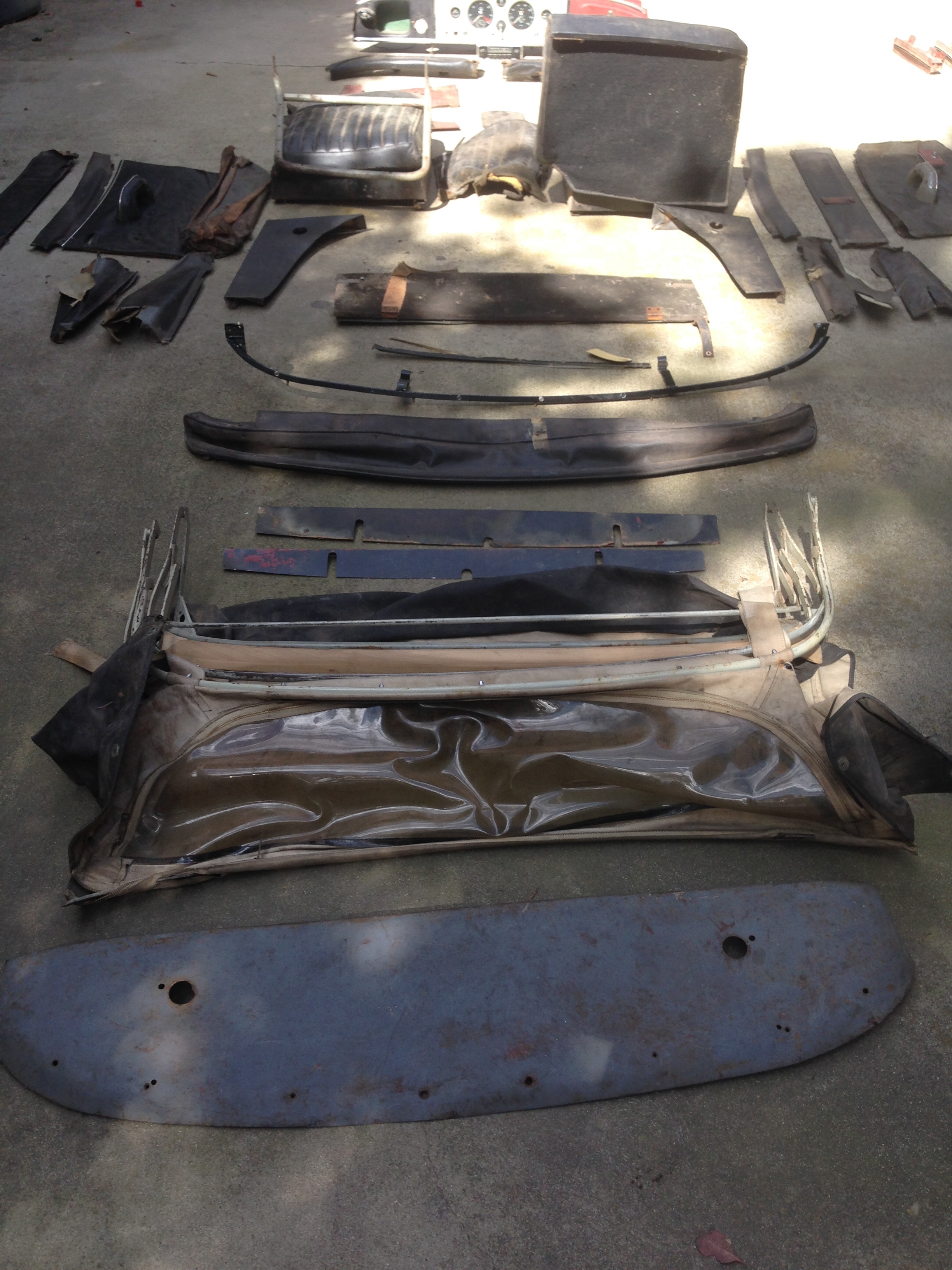
My restoration of 831832 has officially begun. As I mentioned in my first thread, I bought the car in pieces after the previous owner abandoned the project. I flew out to SOCAL two weeks ago to inventory and pack up all the parts. The car arrived earlier this week. Well, the half in boxes anyway…
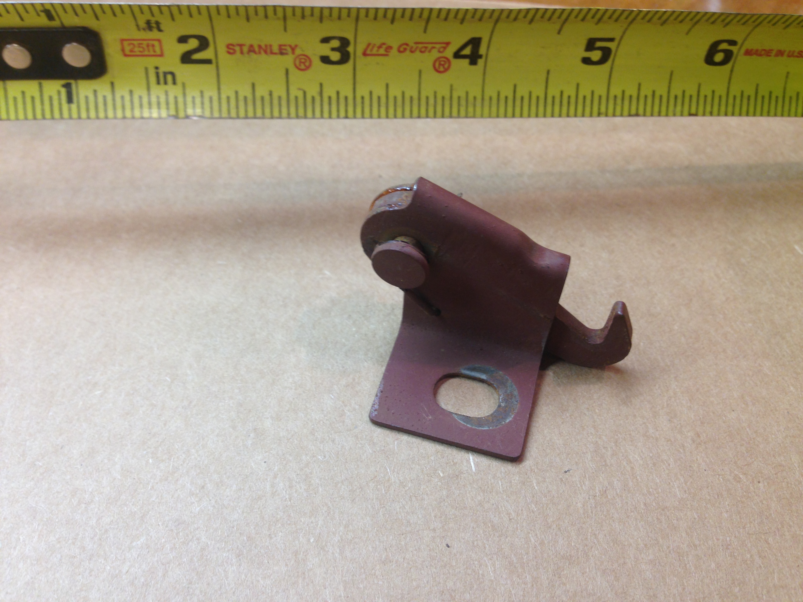
Oh, I’m going to need plenty !! As I’ve never actually seen a 150 up close, my biggest challenge is just identifying all the myriad parts. I was able to disassemble my MKII and put it back together without much trouble, it was like most British cars I’d worked on. But the XK is on a whole different level. For instance, what is this for?:
I thought is was part of the boot latch, but I can’t determine for sure. I’ve searched the spare parts manual, the SNG diagrams, and some reference photos I have. Can’t find it anywhere.
Very exciting. I found my first MGA in 2013 as a basket case. It was disassembled in 1997 and went through 2 owners in that state. Daunting, but not impossible.
I haven’t tried the radio, I’m hesitant to put power to it until I can have it properly sorted.
But the frequency band doesn’t look like North America to me.
Now when I restore a car (if intact) I restore the parts as they’re removed. This keeps a pile of parts from looking insurmountable. It also allows for a speedy re-assembly.
There’s nothing that kills momentum faster than having to de-grease the front suspension after installing the interior.
Well that hook gizmo does not belong on a 150, the closest item which looks like that is the bonnet hold down clip which is located just in front of the radiator , but that is not it.
You are welcome to contact me off line. Email previously sent.
Do not, do not, do not put power to the radio until capacitors have been replaced. Seriously. Go to antiqueradioforum.com and post your query after joining up on the radio discussions part of the forum and let the guys there with decades of experience walk you though it. Capacitors short internally with age and you don’t want to burn up other parts as a result of powering it up “just to see if it works”. I’ve been messing with radio since I was a kid (KJ6OFC here) and have experienced this so very many times as a kid before an old timer wised me up so it would be a shame to read of your radio becoming toast.
I think the radio is a British made Motorola. World Radio Ltd. had a licence to make car radios under the Motorola brand name which extended to the period Radiomobile owned them. I’m not familiar enough with valve Motorolas to identify the model but it was clearly a version of a standard radio personalised for Jaguar. My guess is that if you look carefully, the Jaguar emblem is an insert that can be removed. This is where Motorola normally put their badge and it was designed to be removable so the radios could be customised.
The reason that the scale looks unfamiliar is that it’s backwards. British AM radios are marked in metres and our MW band scales are normally from 200 to 500 and we like to see them ascending from left to right. US MF band radios are always marked related to kilohertz 5.4 to 16 or something like that but you also like to have the low numbers on the left. However this radio is a British radio with a special scale for the US market but the manufacturer has not gone to the trouble of re-engineering the radio, they’ve just changed the scale so it seems backwards to you.
I would heed the warning about powering it unless you know what you’re doing. There are a bunch of capacitors that I always change in these radios when I’m upgrading them particularly in the vibrator circuit.
Absolutely.
I’ve worked in and around electronics since High School. Both units will need a thorough going-thru. In addition to the ancient caps, I also suspect the head unit probably has Silver Mica disease in the IF towers. Luckily, the head unit has a schematic pasted inside the case. Even luckier, there’s a vintage audio repair guy just across the river in VA. I’ll take the lot over to him this week and see what he can do to revive it.
Thanks for the info Morris, that’s reassuring. I did find the spring loaded bonnet latch.
This little hook has a spring as well. It was mounted on the car somewhere, but for the life of me I can’t figure out where OR what the heck it was supposed to do.
Knowledge of Silver Mica disease. That alone tells me your radio is in good hands. Congratulations on your find. I’d love to have a car radio with tubes, er, valves in it again.
Does anyone have a picture of the fasteners that attach the headlight buckets to the body?
Moss doesn’t carry them but says they are “standard items” available at a hardware store?
Thanks for the quick response Bob.
I think it’s the screws (?) that hold 9 & 13. I’ve got the long adjuster screws.
But instead of Part #9 in the diagram (or in addition to it), I have the traditional headlight buckets: