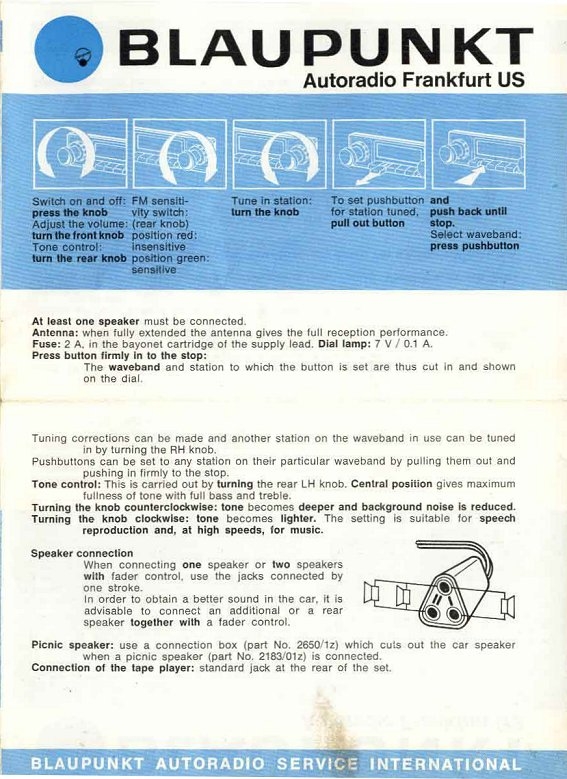
I’ve had a thread going about my restored Blaupunkt TR Frankfurt De Luxe 32471 but this is for a specific question on wiring the speakers. I’d like to confine this thread to just speakers so as to sort out this issue. We all know these radios were dealer installed so there is not only inconsistency between installations but some speakers may be improperly wired by the dealer (mine was).
My radio was wired to the pin-outs as shown here. Call this Pic A:
I understand that the radio requires 8 ohm speakers but I cannot find an official reference to that requirement.
There is another drawing that John Carey uploaded for a more recent vintage Blaupunkt radio (mine’s from 1962) that shows a 3-wire speaker connector (available in 1964) and a wiring diagram that shows one pin alignment with a single speaker and the other pin alignment with two speakers wired in parallel. Call this Pic C:
Finally there is this pic from a different model Blaupunkt than mine but that shows the description of hooking up an “additional” speaker. Call this Pic D:
Here are my questions:
Re. Pics A and B. Which is correct?
Re. Pics A & B, if this is correct for my non-stereo radio would I wire this way with two 8 ohm speakers? Not in series, not in parallel, just separately connected.
If I use just one connection, is there any reason I cannot wire two 4 ohm speakers in series so as to create an 8 ohm impedance.
On impedance, I understand that impedance has a variable content that is frequency dependent. Whereas resistance is simply a static, linear measurement. This means that were you to wire a single 4 ohm speaker to the radio’s amplifier, at very low frequencies (like bass notes - especially if played loudly) your speaker output may approach a DC (direct current) signal…almost a short circuit. That will damage the solid state transistors. So we don’t want to do that. But two 4 ohm speakers wired in series should be perfectly fine (except for a high frequency roll-off you might not get with a single 8 ohm speaker). I am stretching my level of knowledge in this area, so please correct me if I am wrong.
I’ll start with these and see where the thread leads; I do have more questions depending on the answers.
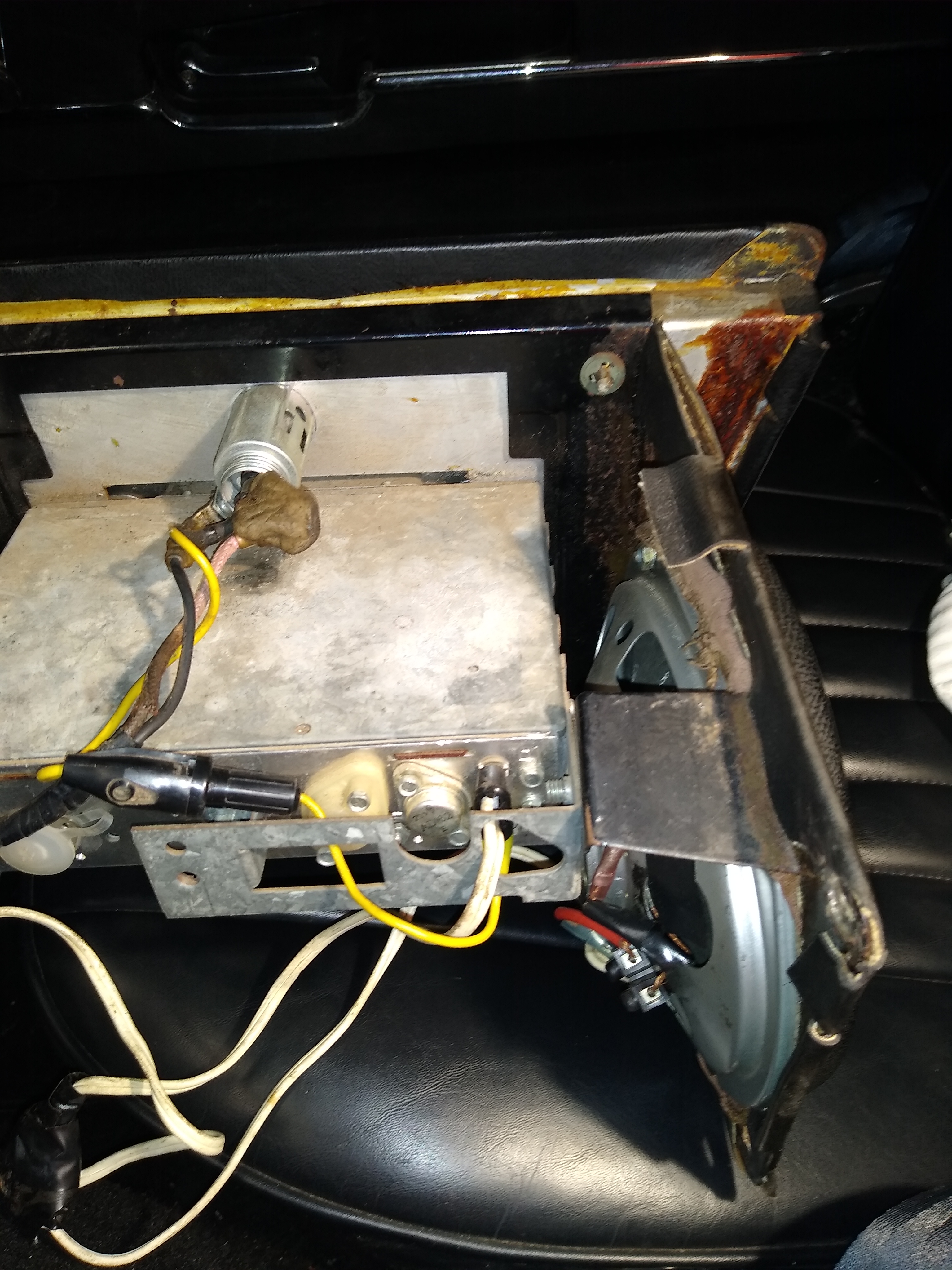
In case it helps here are photos of my car built Feb 1968 and sold from the original dealer Aug 1968. I can see a sticker on the side that says it is a Frankfurt. If you need the model number I can try to get some better light to see that sticker. The yellow wire from the cigar lighter housing with the fuse housing on it disappears into a hole in the back of the radio. The white speaker wires have a connector on the back of the radio. All the radio wiring looks pretty cheesy to me but as I said before I think it sounds good so have never messed with it. My console comes out easy so let me know if something else from my radio might help.
I’ve no specific info on this radio, but I will contribute some generalities that might help a little. You have a good “feel” for speaker impedance. Yes, two 4 ohm speakers (usually reading about 3 ohms on a DC ohmmeter) wired in series is equivalent to 8 ohms.
I don’t know how the speaker jacks are wired. If they are intended to be referenced to ground but are out of phase, then connecting across the two “hots” would give you a signal. If they are identical, then connecting hot-to-hot will give you nothing.
I noticed from your other thread that there are three power transistors. For mono, this suggests that most likely they are in parallel (with appropriate resistors in series with each to allow for different transistor characteristics). The most common configuration in the sixties was to bias the transistors so their output was 1/2 the power supply voltage–about 6 volts. The speaker, connected between the output transistor and ground, would have a constant DC current applied, displacing the cone from centre. Speakers were designed to accommodate this. To avoid this static displacement, a large capacitor could be connected between the transistor and the speaker, but this was expensive and bulky. In either case, the power (which you asked about in the other thread?) is limited by the voltage excursion–it can swing negative to about zero and positive to about 13 V. So that’s 13V peak-to-peak. That’s twice the square root of two times the RMS voltage, or 13/2.828 or 4.6V. Power is Vrms squared divided by Rspeaker or about 2.7 watts for an 8 ohm speaker. You get more power with 4 ohms of course. You can also upgrade the power amp portion with “bridge” amplifiers that can deliver about 30 watts, still operating from 12V. IMHO.
Thank you David. No need for the model no. as yours is later than mine but earlier than stereo which did not come out until the 1970-71 year. I think this looks close to your radio. The Radio Museum says it is a 1970 vintage, but close enough. It is not stereo because they said stereo on the face.
Frankfurt US 7.639.670 ab 1800001 You can see a pic of it at Radio Museum and it looks just like yours.
From you pics it appears the radio speaker output goes to the black tape connector (probably that triangular plug) and from there to each speaker. So each speaker wired individually and they are probably 8 ohm speakers. Be nice to know what brand those speakers are, but I doubt they’d be available now. I also doubt they have a brand name on them. Don’t spend and effort on it.
Here is the comment from Michael on impedance from my other thread: Michael_Frank
You can’t measure impedance with an ohmmeter. Although impedance(Z) and resistance® are both quantified in ohms and aren’t completely unrelated, impedance applies to AC signals. It’s not going to be the same as DC resistance. It’s going to depend on frequency and is measured at 400Hz. You can buy a meter which reads impedance, but it’s unlikely an ordinary VOM will be able to do it. But you can reliably say that the effect of two impedances in series will be additive. In parallel it’s more complicated, depending on how many speakers and what the impedances are: 1/(1/Z1+1/Z2+1/Z3…), so four ohms for two 8 ohm speakers in parallel.
I would expect that if the amplifier is designed to drive two speaker chains, then each chain would have about the same combined impedance. This should be verified by the manufacturer’s documentation. If you end up with a low impedance speaker chain, it will place a higher load on the amplifier, which may or may not have consequences.
So commenting on Michael’s post, thank you for posting and refreshing my rusted out memory. So yes, the impedance is an AC parameter whereas Resistance is simpler DC parameter. Using a pair of 8 ohm speakers in parallel is not something I’d consider for this installation, but adding a pair of 4 ohm speakers in series is and as in that case the impedance is additive, it should allow one to safely do so with this radio.
However as I now know I have two output jacks that can be used simultaneously, each rated for an 8 ohm speaker, that seems to be the safe way to go.
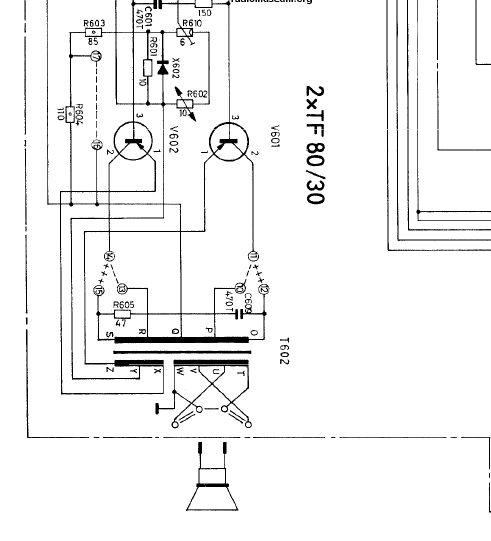
Here is the speaker output circuit for my radio. The annotations are German.
Robert. Thank you so much for your input. Very helpful to me. I did measure the speakers I have around the house and all of my 4 ohm speakers measure about 4.3 ohms on my Fluke. I also have one 8 ohm speaker and it measures 8.2 ohms and a 16 ohm speaker that measures 16.3 ohms. So I have felt that using two of my 4 ohms speakers wired in series would be safe to test the radio.
I’m interested in your comment about the speaker outputs being referenced to ground and that if I connected across the two hots I’d get a signal. Apparently that is what has been the case since the dealer installed this so many years ago. I’m not sure what you meant by, “if they are identical…” though. You mean if they were across the two grounded “legs” ? Either way, what I think I understand is that the two pin-outs my wires were connected to must by the hot legs and the other two are the grounded legs. As a note I find it disturbing that a manufacture would have a pin-out scheme that you could hook up on the diagonal or vertically with the same sized connector. Unless of course, that is how they expected it to be used.
In this radio the dealer installed the two speakers, statically measuring 4 plus ohms each wired in parallel. When I measured that I read 2.7 ohms and that is just wrong. Nonetheless, the radio seemed to survive. As Michael said, “may or may not have consequences.” Still I don’t want to stress this 60 year old amplifier any more.
I also found it interesting about radio designers biasing the transistors and the derivation of a potential 13-volt excursion limit (essentially the battery voltage) and the calculation of the power output. (Jeez, I forget all this stuff from 53 years ago!) Anyway, on my other thread I posted the specification on this radio. That came from Radio Museum and its says 4 watts power output. At the bottom of that spec. is posted an actual measurement of the power output at 12 volts and that say 6 watts. They don’t state what load they had on the amp output to conduct the test. And then there’s the possibility of replacing the power amp portion with new bridge transistors. Is that even possible with this radio?
I’m not certain of how to match a speaker to an amp, but I believe it best to keep them fairly close so as to deliver the best sound. You need to move air to get good sound. I’d guess a pair of 8 ohm speakers rated at 10 or 12 watts peak each should suffice. If correct, this is where I’ve been trying to get to rather than just listening to folks who want to sell you speakers. Those might be hard to find, but finding 20 watt speakers is easy and that might close enough.
Does anyone agree with this? Find two 8-ohm speakers rated at 20 watts peak or less.
Very kind of you Scot, but it looks like much of what I said is completely wrong! In the early sixties, transistor radios replaced tube (valve) radios in many cars. These operated directly from 12V, eliminating the vibrator/transformer/rectifier needed to step up the voltage for tube radios. Power transistors (only PNP available at that time) were directly connected to drive the speakers as I described.
I assumed that your Blaupunkt had retained the tube-based tuner section but substituted a direct-drive transistor amplifier of then-modern design. But the schematic posted above shows I was wrong. Basically, it looks like Blaupunkt retained their tube-type amplifier section, except they substituted a pair of identical PNP germanium power transistors for audio output tubes. The configuration is “push-pull” and utilizes an output transformer just like the tube version. The transistors drive the transformer centre-tapped primary, and a separate secondary is used to provide negative feedback back to the transistors, similar to the “Williamson” circuitry common in tube audio amplifiers. And, as in tube amplifiers, a separate secondary drives the speakers–one side is grounded, and it has two taps. These taps are often used to supply different impedance speakers–4,8, 16 ohm for example. It looks like they are configured here to drive a pair of speakers, each one from a separate part of the secondary.
Long winded, sorry. But bottom line is that incorrect speaker impedance choice with a transformer output won’t hurt the transistors. It might give more distortion, less volume, and less “damping factor” which is not necessarily bad–more bass, but not as “tight.”
I’d ignore speaker power ratings–they are a farce IMO. What you want is efficiency–sound output per watt input. A high efficiency speaker can blast you out with 100 mW input. A low efficiency speaker might be called a 100W speaker because it can absorb 100W and produce very little sound. All IMHO.
Would it help if I sent you the full schematics for this radio? I’m not allowed to publish them, but I can send them individually.
On the high efficiency I’d agree exactly. I just didn’t say it well. I don’t know how to find speaker efficiency ratings but often see the related sensitivity. I believe a speaker over 90 db sensitivity will be more efficient and probably louder than one rated at 85 db for example. And that 90 db is a good rating to look for. How does that relate to efficiency…or rather, what should I look for?
Scot I still do no know brand of the speakers but at the top of them in English it says MADE IN GERMANY. Here is photo of only other markings I see. Both of them appear to say FL1818/19/85 but the last two characters are not very legible on either speaker. Could be 8 or 6 or 5 or 9 maybe. Expand the attached photo and make your best guess.
I doubt if I could add anything by seeing the schematics, Scot. But yes, that db rating is what I mean by sensitivity. It is the sound pressure level (units, db) one meter from the speaker when it receives a 1 watt input, typically a 1 kHz sine wave. The actual sound level depends on the speaker enclosure as well as the speaker itself. Bigger cone, soft foam “surround”, strong magnet, large excursion all mean more sound per watt.
Not too relevant here but when you’re serious you want flat frequency response too. This is often achieved by means that reduce the sound output overall in exchange for flattening the response–like so-called acoustic suspension.
thanks David! I searched a bit but didn’t come up with anything. I find it interesting that you’ve oval speakers mounted instead of round. You know your ‘68 FHC is a match to the car I drove from Phoenix to Huntington, Long Island in August 1968. I sailed boats when I was 21 and had taken an 80’ ketch from Acapulco to City Island, NY went home (Scottsdale) and that owner asked me to drive his brand new XKE that was in Phx to the L.I. Black on Black, no radio. What a great drive that was and the '68 remains my favorite.
Thanks Robert. You’re a wealth of info on radios! Back in engineering school I had designed and built my own home speakers (the cabinet and cross over really) using Radio Shack speakers in a low-power application (Sony reel-to-reel player using a bass reflex design. They sounded great but I never took the interest any further. The days of youth, huh?
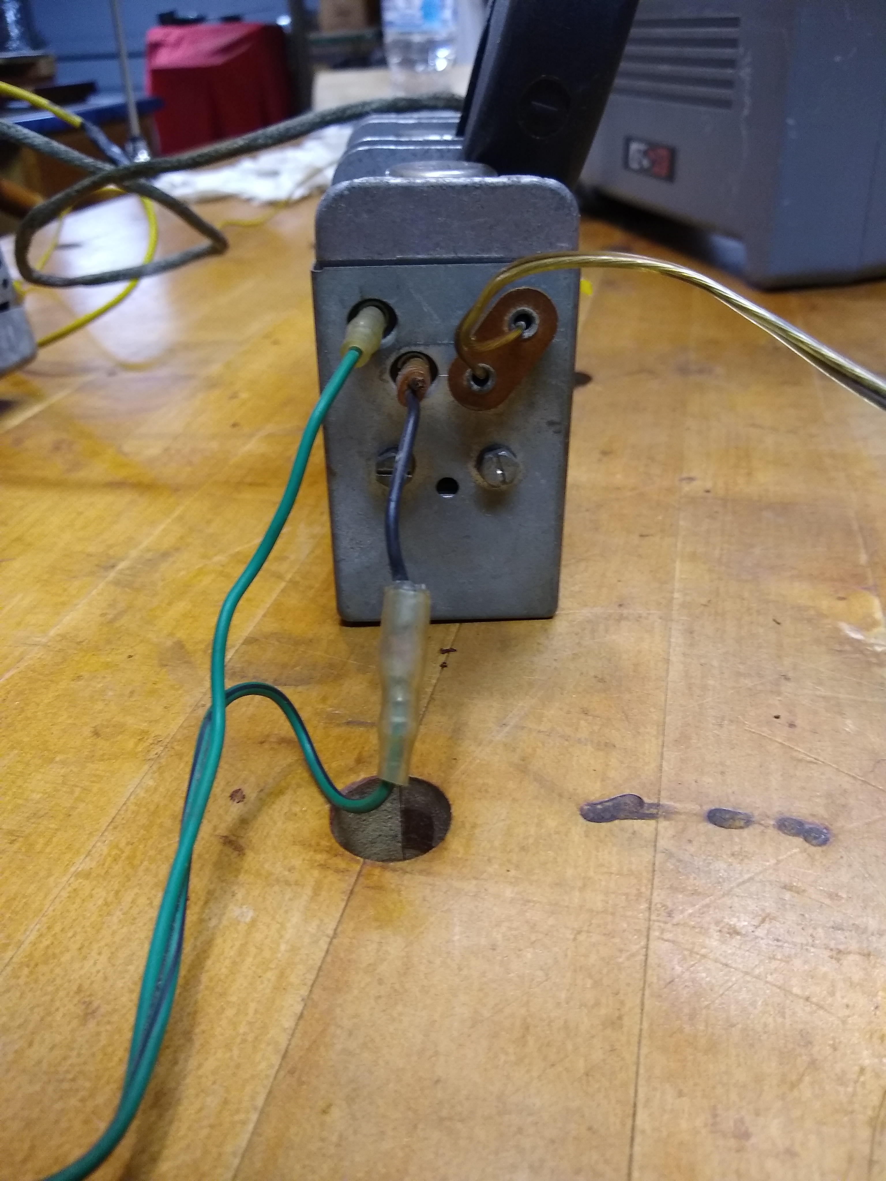
Back on topic and my first pictures: do you know how I should test the speaker outputs from the connectors I have? Blaupunkt warns to not power up the amp without at least one speaker connected, but can I then measure the other side? What might I look for?
What do you think of the idea of using to 4 ohm speakers in series to achieve the 8 ohms Blaupunkt seems to want? 4 ohm auto speakers are much easier to find than 8 ohm ones are.
And on the theory side, if a speaker is rated for high power, say 160 watts, even though that may be a “marketing” number, isn’t my 4 or 5 watt amplifier going to have a tough time moving the coil? Even if the speaker has a 90 db sensitivity rating?
As mentioned before, this works fine. Both the DC resistance and the impedance will precisely double. Be sure to wire them “in phase” or you’ll lose bass.
IMO, no. The sensitivity rating prevails. A good example are the Klipsch or Altec-Lansing horn-loaded theater speakers. They are about the size of a refrigerator, and rated 200W. Sensitivity is 97 dB (just looked up the specs of the Altec)! A friend had one in his college dorm room (next door to mine) and drove it to more than adequate listening volume from the ~200 mW earphone jack of his 1960’s pocket-sized transistor radio. We connected the same speaker (placed facing an open window) to my 70W Eico power amp, and used it to blast ear-splitting obscenities (and Bach organ music) to an adjacent dorm 100 meters away.
I don’t come close to understanding the current power claims of loudspeakers. No speaker can dissipate very much power in “free air.” So does the power rating specify a particular enclosure? Also, is it continuous power (like the 200W spec of Altec-Lansing “Voice of the Theater” speakers I cited above) or “peak” power. The latter is very misleading, as it is defined as energy dissipated per unit time (watts = joules/second) but not continuous. So a speaker might consume 100W for 5 milliseconds during a cymbal crash without overheating, and possibly with a lot of distortion.
Digression: Peak power is a misused spec for electric motors, too. Sears Craftsman is/was famous for this trick. I just looked at my vintage Craftsman shopvac and is says “3.5 peak HP.” Same goes for my radial arm saw. What they mean is that, if the saw is running at speed and you jam the blade into a chunk of metal so that the blade comes to a stop in 10 milliseconds, during that 10 ms the rotational energyi of the blade is dissipated as heat, so that the power generated is brief but enormous–giving the “peak HP” rating. It’s like the power generated by a 100 HP car during the time it collides with a wall–its mainly the speed and mass, not the continuous power rating of the motor.
Regarding testing the speaker outputs from your connectors. I can’t help much. You can use 8 ohm 2-5 watt resistors instead of speakers if more convenient, and observe the signal with an AC voltmeter. You might also measure the resistance among the W,V,U, and T taps on the output transformer shown in the posted schematic. Are these all the same (W to V, U to T, etc). It looks like they want a single speaker between W and T? That could be two 4 ohm speakers in series.
Good luck! I assume you want originality…otherwise you could easily replace the amp section with something more modern.
I knew that would be the answer. The sensitivity rating is not dependent on speaker size. But I like your refrigerator sized dorm battle! Wayward youth, heh? I have some Klipsch speakers, KG-1s I believe, that I commandeered from a TV application to use on my music PA system in my studio. 90db , 2-way, 50 watts/250 peak, 8 ohm. Klipsch makes very good speakers. I would have like to heard that beast you and friend had.
I do understand the problem with the peak ratings. Just don’t know what it really means in terms of speaker sound quality. Just a number.
Now this is of interest. Firstly it is how my speakers were wired so I know it works and I don’t see any real benefit in sticking to two 8-ohm speakers wired individually that deliver poor sound when I may be able to find higher quality 4-ohm ones. If the radio were stereo that might be a different issue, but it is just hi-fi. I’m searching!
I guess on the measurements what I am after is to find which terminals are the signal. I don’t really understand that schematic because I don’t know what those two heavy horizontal black lines stand for. But, I see that W and T are the grounds, therefore V and U must be the signal. So, keeping one 8-ohm speaker connected, say to T and V, I should be able to measure the the AC output of U and W.
Robert thank you for you time and expertise, it has been very informative.
Thank you Bill. I’m ashamed I had to ask. And thx also for the link; I’ll read up on transformers.
I want to thank EVERYONE for helping me out with this query. And hopefully this thread will help others in the future.
I have decided to go with an offering from TurnSwitch. Their speakers use superior magnets, have great sensitivity numbers and are custom made for them. They are price MOL the same as the big name brands but, I believe, are better value. In my case I’ll get a pair of their 8-ohm, 4-1/2" speakers with neodymium magnets and a sensitivity of 92db…which is excellent. I’ll hook them up like my Pic B above making sure they’re in phase. I’ll report back when I hook them up.
Scott,
Make sure that the depth of the speaker’s magnets will not interfere with the radio chassis. I searched a long time to find speakers of the correct diameter and depth. I found mine at www.turnswitch.com. Good luck with this project.
To wrap up this discussion in hope it will help others in the future, I’ll summarize. I am quite certain of my findings but there is no guarantee. It is very interesting to note that no one I have discussed this topic with, including radio engineers, speaker engineers, the Radio Museum Organization, trained Blaupunkt technicians and a handful of knowledgeable folks have any documentation from Blaupunkt that categorically define the speaker requirements. (They are thought to be 8-ohm speaker required.)
The car in question is a Series 1 XKE coupe built in September, 1962. An “early” model.
The radio in question is a Blaupunkt Frankfurt TR de Luxe 32471. This has a remote amplifier that has 4 speaker output pins. These pins on my particular radio are arranged such that the speaker(s) can be attached as in my Pic A for one 8-ohm speaker, or Pic B for two 8-ohm. (Some other Frankfurt models have 3 pin-outs for the speakers, but they function the same way as mine with a different style of jack.)
This may seem confusing as one might assume the speakers can be configured in a parallel arrangement as shown in small diagram in Pic C. But the way the transformer taps are designed as in my circuit above, [quote=“ScotThompson, post:5, topic:396877”]
speaker output circuit
[/quote] allows for the use of 8-ohm speakers whether a single speaker or a dual speaker.
I had my radio cleaned and fixed by VintageBlau (.com). They informed me the “traditional” way the speakers are 8 ohms and connected as in Pic B. I searched for speakers that would fit the factory grilles and after much research I found that the folks at Turnswitch (.com) which is S&M Electro-Tech Inc., are very well versed in speaker design and “know” their vintage radios. Speakers performance is perhaps best measured by its sensitivity rating. A sensitivity of 90db or higher is excellent. The 4-1/2" “Pin Cushion” speakers I bought from Turnswitch are designed and made in America, have a 92db sensitivity, use a neodymium magnet and have a whizzer cone all in a 1-7/8" depth package. Note that on the early 3.8 cars the grilles are concave by 3/8" and these speakers fit without interfering with the grille. The speakers are rated for 40 watts. I have powered up the radio on the bench with these speakers installed in the console and also installed the radio to assure they fit. They do. And, given the size constraints, they have a good sound and are quite loud. They will even sound better in the car because more “backside” sound will be prevented from coming around the console and conflicting with the front facing speakers.
Well after 54 years the Blaupunkt Frankfurt AM/FM in my 68 started acting up (some photos of it above). In May I had the on/off switch and tuner repaired. Then a few weeks ago the speakers quit. Using the info above (thanks very much) I got 2 of the 5"x7" OVAL speakers from S&M Electro Tech. They are exactly the same size as my originals and fit right on the existing speaker studs in my console. The only real difference is that the magnets protrude on the back which was not a problem for me since they still cleared the radio see my new photo below with an original speaker on the left and new one on the right. The sound is fine and very similar to my originals before they gave out.