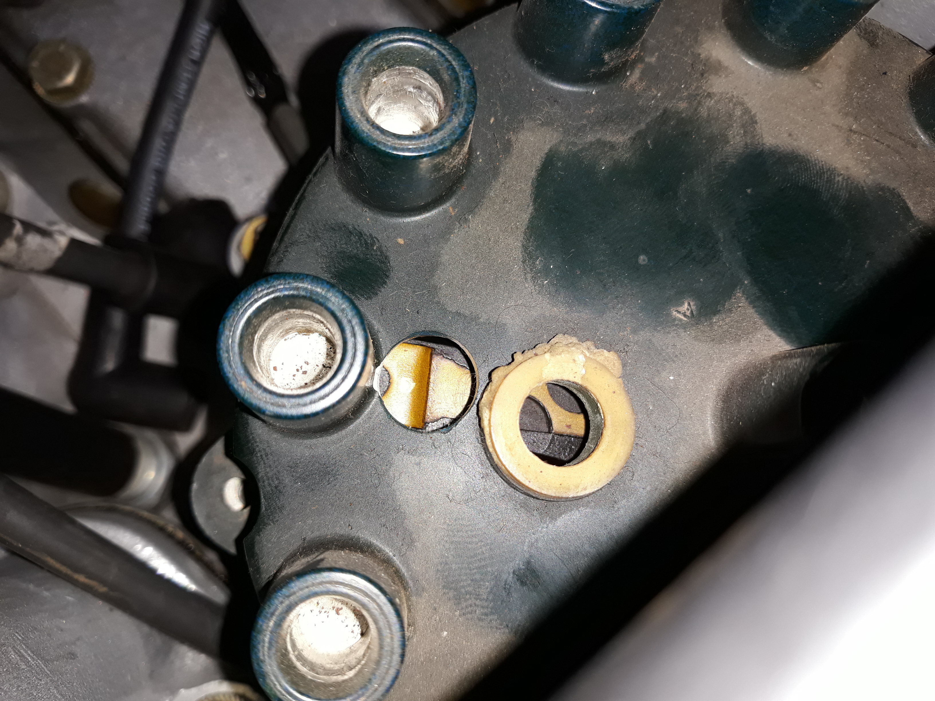
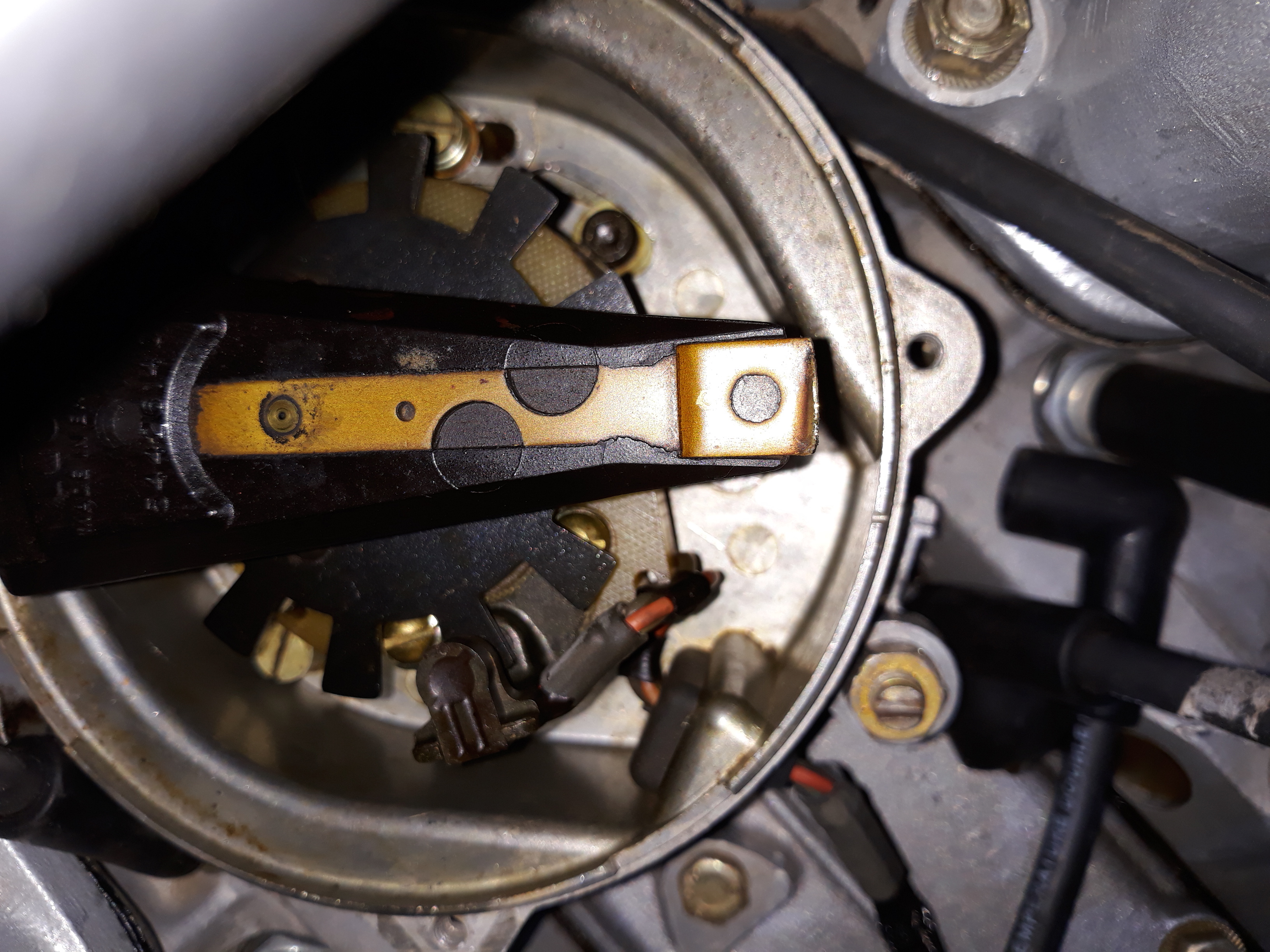
As mentioned the MC3334 IC itself has threshold on/off at 1.8V/1.5V.
GM may have added some circuitry in front which modifies the levels, but not likely to be significant.
The mention of 1.2V and 0.9V in the pdf file is another matter. That relates to putting a steady DC on the input of the GM unit which does not happen in normal use. I just found by accident putting a steady DC above 1.2V on the input really heats up things very quickly. Important to me and anybody using the GM unit with an aftermarket EFI system.
I configured the Motec unit to drive the GM unit with a signal between +0.5V and +5V. My bet is any signal from about +0.5V to +3.0V would work safely. Also the Motec unit uses its own logic for dwell control.
In the pdf file I had the GM unit on the bench with coil and spark plug attached. I used a signal generator to drive the input at +0.5V to +10V, and I varied the duty cycle. You can see the on/off of the coil was synchronised with the input pulse waveform. Ideally you always want the coil primary switched on ( its -ve terminal switched to ground ) only long enough to store the energy you need to create a good spark. Keeping it switched on longer just heats the primary winding. Also you want the current to be limited which the MC3334 can do.
I was using a Bosch low impedance coil, nothing special, and got reliable spark up to the equivalent of 12,000RPM. In an engine the spark characteristic could be different and might not get to 12,000RPM.
That 12,000 RPM does show only 0.5mS is needed to charge up the coil.
It also shows the low RPM operation is very wasteful if the coil is switched on as long as the pdf file shows. I would have to do more testing to see how the GM unit works with an actual dizzy signal, and how the dwell time is controlled.