I was bothered by this thread so I dismantled mine this morning to investigate…
Jim, my experience with the new tapered pins is that the taper angle does not match the hole on original shafts (too much slop) but it does match on same-source replacement cross shafts. So, either purchase a new replacement cross shaft from the same place you purchased the new pin(s) from or, you can do like I just did: make your own pins out of known metal stock (as who knows what grade of steel these new pins are made from?). I ended up turning a few automotive (Grade 5) steel bolts on my 90-year old lathe until I achieved a taper that was spot-on. With the new cross shafts my taper was a little over 1 degree from 90 at the compound rest. It’ll be a trail and error thing. Finally, I used a dab of valve grinding paste to ensure the parts were seated just a little bit better but that may be overkill on my part.
Thanks for the reply.
Are the holes in the shaft parallel ?
Holes in the shaft parallel? Parallel in relation to what? They are offset from each other because the cross shaft is made to accommodate either a LHD or RHD car – if that helps. Only one of the two holes will be used. From watching your video I can tell you that one side of each hole is supposed to be bigger than its exit. The larger side is where your pin is supposed to enter. This is because each hole has a taper to it. As your example pin is still wobbly while pressed up to the shaft, this tells me that there is either a taper mismatch between pin and shaft and/ or your cross shaft taper hole has wear. A pin with a correct fit should never have its threaded portion meet all the way up against the cross shaft. It can be very close – but not touch. It’s too bad the fork doesn’t have provision for an exit hole as this would also help in establishing whether the pin is seated properly.
Here is the outside end of my cross shaft. It too is prone to developing pin shear issues. Per previous postings, I’ve addressed this by turning and welding a sleeve to the back side of the fork and making a pin that runs all the way through instead of ending somewhere halfway into the shaft.


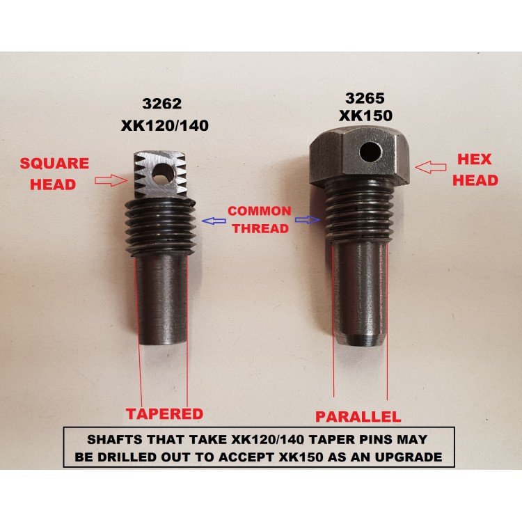
I should have asked if the holes are straight or tapered , rather than parallel . I am tempted to go for the 150 set up . But I am confused , I would have thought a tapered pin in a tapered hole is stronger than a straight pin in a straight hole ? Picture taken from Coventry Auto components. The SNG picture shows a spring washer under the bolt head of the straight , so it locks up like a standard bolt , where as the tapered pin locks up by being tight in the hole , so in theory the fork cannot rotate on the shaft .
Correction , the SNG shows a spring washer , but where that fits is unclear
1 Like
I can’t speak for others, but as mine is a 120, I stayed with the tapered pins/ holes set-up. The pros and cons of both almost seem academic. Going with the 150 set-up sure makes things simpler though. I know I spent a good 10 hours making, threading, turning and lapping about a half dozen pins until I was happy with my results. At a certain point you just want to be done with it and move on.
I don’t think that 150-style pin should have a lock washer under it. If so, then why drill the head to take safety wire?
This where I am up to now. Still not sorted. I will look at some new shafts and pins today to see if that is a solution.
Assuming that’s a new release bearing, could you measure the depth of the carbon ring for me please. ? Just do I can compare a new one with the one I have out at the moment.
I have my Mk9 in bits at the moment and had the same problem with the lever fretting on the shaft.
I drilled it out parallel, and made a parallel pin which goes all the way through from an old bolt.

Video part 2
I thought it would take me a couple of hours to remove the gearbox, check it over and refit… It took 2 days.