Then why the need for the high frequency oscillation circuit???
I think the high frequency creates a capacitive “reactance” from the small capacitance that exists between the pin and the fluid which becomes measurable …and if the capacitance changes when the water disappears then the circuit detects the change somehow and lights the light.
It is Electrical Engineer territory…I have someone I can ask who will know for sure…
A DC voltage causes electrolysis that’s why they use an oscillator. I
don’t think the nand gate IC can drive the bulb as the don’t pass enough
current, so there is a small transistor to drive the light. It was
probably 15 years or more ago that I repaired my low coolant sensor, so
a bit hazy! I recall just one IC which I changed. Capacitors are many
different types, only the electrolytic type fade with age. Leave the
others alone. ICs of these types are usually damaged by negative
surges, possibly when jump starting from another car.
Jim (retired electronic engineer) Brighton UK
yes, that one can burn too
iirc there 2 big (relatively to the others) tantalum capacitors,
changing those with the IC and transistor gives you a brand new controller
I wouldn’t look forward to that soldering job. First ya gotta get the old IC out without destroying the PCB. Then ya gotta solder the new IC in without burning it up. You guys wanna share your secrets of doing this successfully?
Oh, and where do you buy IC’s? Is that a mail-order item, or easier to buy locally?
It’s a super-common CD4000 series CMOS IC–available anywhere, like Jameco or DigiKey. I have a bunch…very cheap.
Hahaha! A piece of cake to desolder compared to modern stuff. Pin spacing is 0.1 inches, not 0.05 as it is now–and only on the sides, not across the bottom too. Heat each pin separately and use a “solder sucker”–there are various ones out there that vary in complexity. Then, the chip just lifts out.
But as stated, could be other components; not necessarily the chip.
I fitted a S3 radiator and header tank to my S1 XJ, and bought this sensor although I’ve not hooked it up. I did cut it open out of curiosity–a Dremel abrasive disk just inboard of the end with the wires. That end, with the circuit board, just slides out of the cylindrical housing–can be easily restored. IMHO.
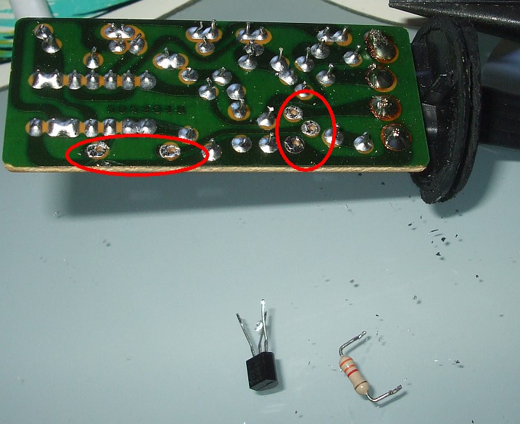
As Robert said it is a peace of cake compared to today’s surface-mount technology. Soldering iron and solder suction tool will do the trick. If you don’t have suction tool you can cut off all the legs and desolder them one by one. Soldering a new component in is the easiest part. Key to success is good preparation. Clean all the old solder from the holes with desoldering brade and use good soldering flux when soldering new components in.
not much to add to Robert’s post
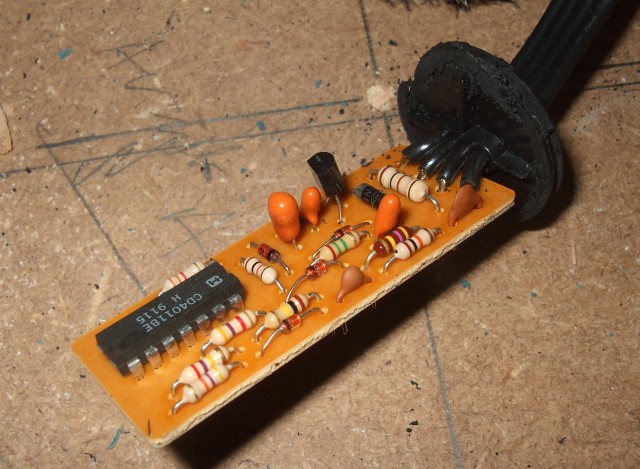
the circuit is very simple, and reminded me of the “electonic kits” I’ve build years ago
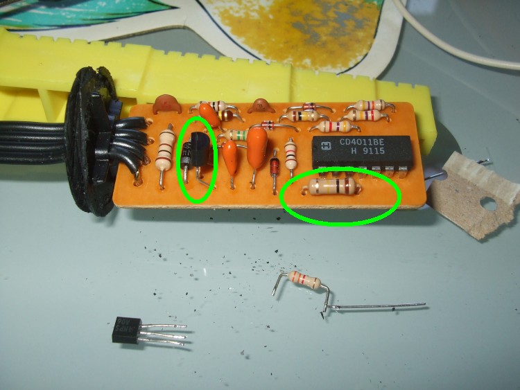
I checked the transistor and it was busted, while the IC reacted normally, so I changed the transistor, and one resistor, as suggested by John_John1
soldering is easy if you’ve done some, most modern electronic stuff is much smaller
the only “trick” was to adjust the transistor legs so they match the previous one, as I didn’t search for an exact match
testing the whole controller is easy with a simple voltmeter , but you need to add a resistor in the ouput as the transistor is operating as “open collector”
It is normally easier to cut the legs off the IC then you can remove
each leg separately.
Jim
Yes…makes sense…so it is a simple resistance based system but needs the complication of the reversing voltage to prevent electrolysis. Sorted.