SUMMARY OF PREVIOUS THREADS I thru VII Part I - Introduction of Hobby Shop and removal of engine/transmission
Part II - Removal of all wiring harnesses, dropping fuel tank, stripping the car of all ancillaries and cleaning asphalt coating from under-body/bonnet
Part III - Engine Tear Down, Removal of Heads, Chrome to Chrome shop, Prep for and actual Painting of the Jaguar
Part IV - this thread covered quite a myriad of topics: A comprehensive matrix of nickel and cadmium platers // Procedure for removing crankshaft // Removing timing chain, guides and tensioner // Repair Timing Chain Cover (aluminum welding) // V12 Exhaust system options // Removal and ultimately Replacing Oil Pump ($$) // Checking Cam Sprockets for reuse // Challenges of removing 6 stuck pistons/sleeves (significant portion of this thread) – including a trip to a machinist; spread over a wide range of posts // Discussion of glass beading and/vs vapor blasting // Return of Chrome
Part V - this thread covered: carbs and dizzy back from rebuild (with contact data) // options for A/C compressor // installed left and right side wiring harnesses and Bulkhead Harness // challenges attaching Bulkhead Harness Grommet (C30670) // Elastrator as a possible tool to solve issue // more on vapor blasting – a definitive discussion // purchased a non-Series III boot lid seal during a group buy to use as a boot lid seal // started install of distributed compressed air from the compressor.
Part VI - this thread covered: processes of wiring new bulkhead harness to the 4x new fuse boxes // variations of Series III Wiring Diagrams // MarekH: Jaguar Wiring 101 // how-to regarding Home Made Circuit Tester for less than $10 // Comparo of newly cadmium bits and tubes to old // rebuilding wiper motor // receipt of new Exhaust System // comparo of incandescent bulbs to LED equivalent // camparo of mechanical brake light switch vs hydraulic // tricks to re-installing pick-up/return lines and the ins and outs of the in-tank fuel filter // receipt of all bits to rebuild heads and choosing a machine shop // YouTube videos covering the wiring of the 10x switches on the gauge panel // a source for better than new Front Upper A-Arms (AKA wishbones)
Part VII - this thread covered: the Terminal Post on a Series III is Whitworth (a 1/4 Whitworth Spanner will be correct) and the proper sequencing of the cables (always put the thick starter motor cable up against the battery positive connection) // the utility of grounding straps including photos of OEM grounding straps locations // a discussion of do’s and don’ts’s of applying Dielectric Grease (its an insulator, not a conductor) // heads are refurbished – machining done // a schedule of lead times for out-sourced procedures // application of ceramic coating on my fresh paint // definitive identification of Horn Relay Bracket // installing LED panels in brake/tail lamps and front turn signals // a pair of restored Upper Wishbones arrive from Australia // THE definitive discussion of dealing with hydrogen embrittlement on cadmium plated parts //
.
.
Getting those two 8-pin connectors through the hole is the worst of it. I have to keep telling myself that getting each wire/wire bundle through the hole makes it that much more challenging.
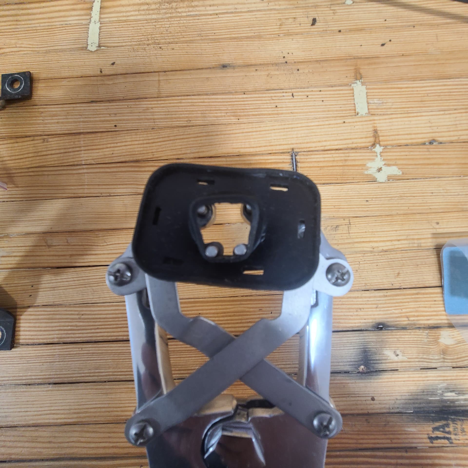
A technique offered up by @Dick_Wells was to use that agricultural tool to spread the opening in the rubber part of the grommet after warming it in boiling/very hot water.
.
.
Others suggested cutting the molded plastic of the 8-pin connectors to make it easier to pass through the opening – I don’t trust myself to make that incision nor reassemble the 8-pins afterwards.
Others said cut through the rubber of the grommet and then just wrap it around the wiring harness – expecting the structure of the firewall opening and the pronged, hard-plastic element to hold it together.
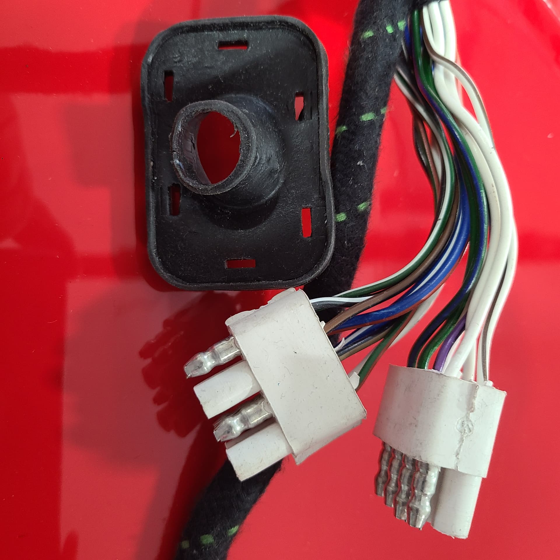
I got a recommendation today that is a hybrid of that final option. I zoomed in on the rubber grommet and marked with red lines where I am planning to cut it. I think this set of “starburst” cuts will allow me to fit even the 8-pin connectors through the opening while being able to close it to its original size afterwards. The cuts would be all the way through inner opening but stop short of the outer rim (between the slits that accept the prongs of the hard-plastic piece).
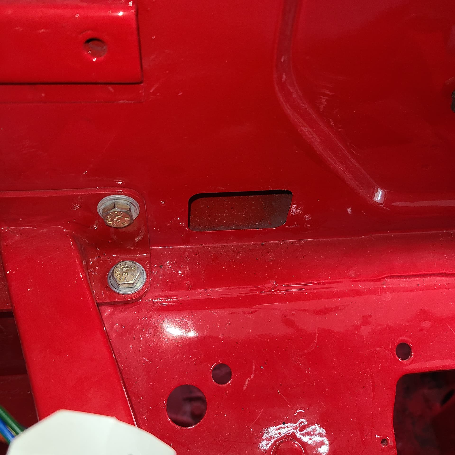
I have the original rubber grommet that is still around the original harness to practice on. Notice that the rubber grommet is inside the bulkhead while the hard-plastic pronged “lock” is visible from the firewall side :
The eight pin connectors are a molded rubber around the pins, so you can’t easily disassemble the eight pin plugs because the liquid rubber wraps all around the pins and their flanges internally. You can cut them in half to be four four pin plugs if you want.
You can check out whether putting the grommet on from the other end would be easier. It’d be a tedious thing to do, but if all of the pigtails and connectors on the instrument gauge ends are simple bullets rather than the double eight pin blocks in the engine bay, then that might work.
You can put a radial cut into the rubber grommet. That’s probably the path of least resistance. Superglue it back afterwards if you want to.
You could also just pre-fit a more compliant rubber grommet to the loom and open out that hole so the more compliant pre-fitted grommet on the back of the inner molding achieves the same result.
Well there you go I’d heat it up and soap it up before I’d cut it up . Someone here has done it and they would know think your in for a wrestling match
I have been attaching small bits and pieces back on the Jag with a focus on those bits that have an electrical connection. I ceased work - for now - on tracing the new wiring harnesses until I have something on the end opposite the fuse boxes to test.
With that in mind, I attached the chrome badges on the deck lid (I know, not electrical, but one less thing to trip over). After fussing about for the better part of an hour, I stopped trying to get the small plastic bits onto the studs of the chrome badging. Either the studs were too big or the plastic buttons too small.
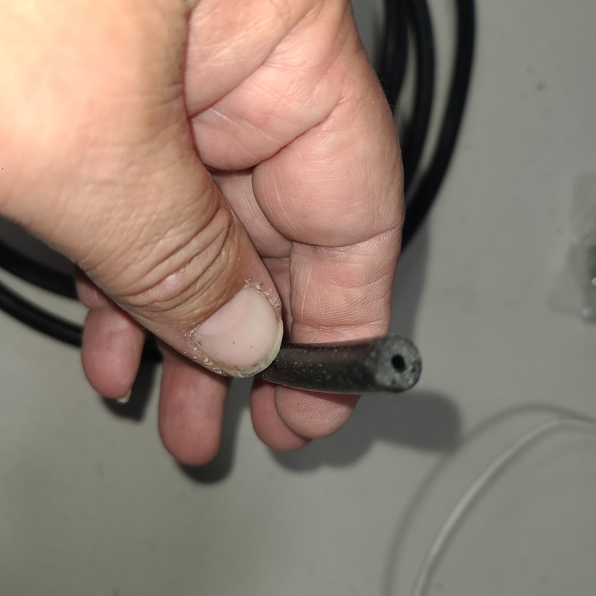
Some one mentioned in another thread about using vacuum line snipped in to 5/16" lengths as the securing device. After trying various sizes of on-hand tubing, I determined
what I had was too big
that I needed an ID of 2-3 mm
that Amazon was my best bet
GOOD NEWS - I found vacuum line with a 2mm ID - works perfectly. I even replaced 2-3 of the small plastic bits with vacuum line. If you are careful and make your cuts at 90°, it even looks factory
I reckon about 9’ 10" (I made 5 of the small plastic bits, but messed up a few times getting the hang of it.)
V12’s need 9 of the small plastic bits (the three studs on the “V12” are slightly thicker than the others). Series I and II need fewer cuz of lesser badging. Anyhow - I have enough vacuum line to do 35-39 V12 E-Types. And I don’t think there is any application for 2mm vacuum line on the V12.
For the cost of postage, I’ll gladly mail the length you need (if I had done all 9 studs on my badging, I would have used 0.3125 x 9 = 2.8+").
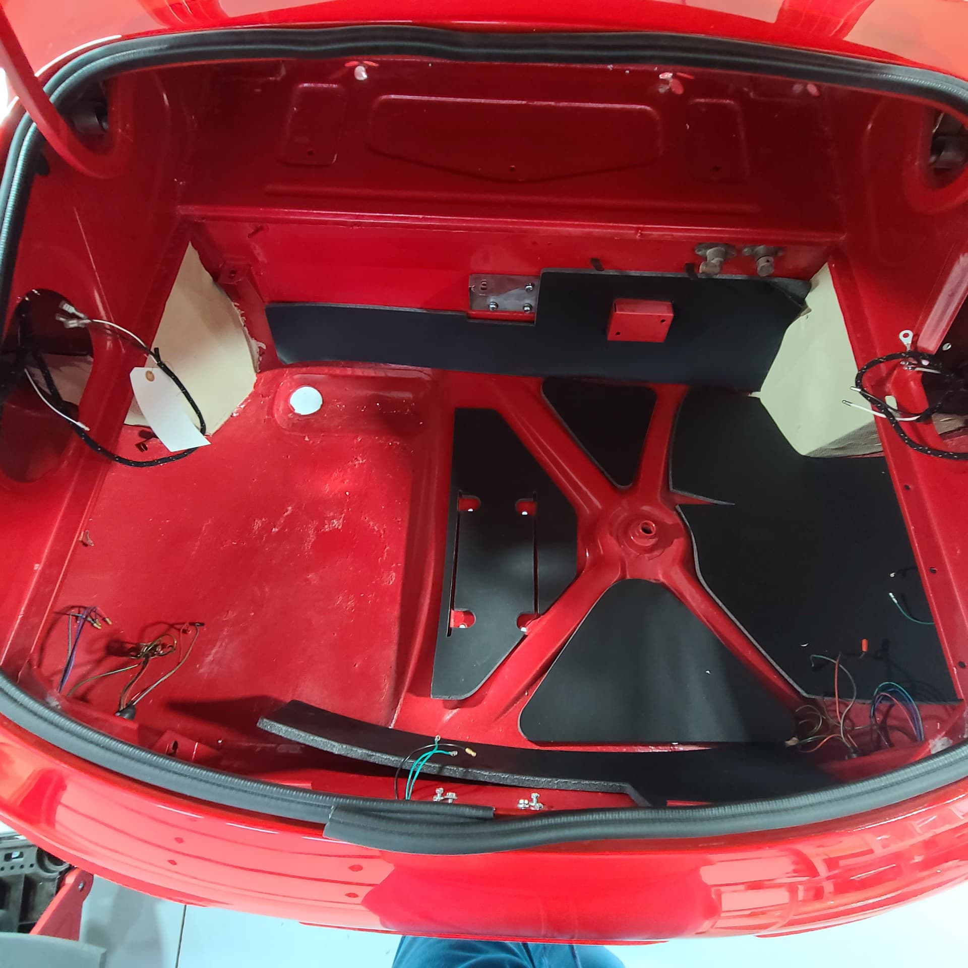
I have been putting together the rear of my Jag with an eye to installing the fuel tank (and its electrical connections.
Prior to installing the tank, I was in the process of attaching the padding that is part and parcel of a Series III. All the pad sections are pre-cut and fit (lay in place) perfectly . . . except one. It seems odd this last one is so poorly shaped. It doesn’t even come close. I didn’t remove this pad so have no recollection of placement to go on.
The pads that fit, do so cleanly and neatly. (Note the hole for the sump of the fuel tank.)
I can’t imagine the 73 and 74 were so different as to account for this level of mismatch. They had identical bodies to my 72 – just the front/rear bumper treatment was changed.
Before I start cutting on it: Any clues out there?
I found the plastic bag the kit came in (never throw away anything).
A search on Part Number CSPJ9204 on the bag does not produce results on any of the regular sites -
BUT - I did get a UK ebay hit: Jaguar E-Type S3 Soundproof underfelt kit Boot Premium Trim 5.3 V12 Petrol 71-75 | eBay priced at 115 UKP = ~$135 plus shipping.
The auction site, oddly enough has a reference to Moss Motors Part Number CSPJ9204 at the bottom. The image of the kit on the UK ebay site looks identical to the kit I received.
A search of Moss Motors website for “CSPJ9204” does not find that item. Hmmm.
I would call Moss Motor with Part Number CSPJ9204 and see what happens
Failing there, eBay-it but pay what I expect is steeper shipping costs from UK. It may be manufactured drama but the eBay auction says “last one”.
Hello Craig,
If you want to Split Hairs, the surface pattern of the kit shown in the ebay advertisement is not right and I doubt that the Robey product will be either. Therefore, I think a DIY kit could be just as good…
Hmmmm . . . looks like the same dead ends I ran across. The Ebay post also says “May not post to United States.”. Bummer!
I did find a U.S. Ebay listing under Moss Motors which led to European Auto Interior for the complete underfelt kit, however, they state that it is made from jute(much like the original I think), and all sales are final. I would think that by now a better material would be available.
Are yours jute or some kind of dense foam product? I could have sworn that I had read somewhere that someone had installed a closed cell foam material that had a black coating which gave the appearance of the original pads. This would avoid the water retention properties of the jute and therefore reduce the chance of rusting. I wish I knew where he got it!
I think that’s the key word.
Bid on it/Contact the seller and see if he’ll send the kit to you.
OR
On Monday contact Moss Motors and see what’s what (why it shows on UK eBay but not their website; may just be an oversight/omission)).
My kit is foam (see photo below) – definitely not jute – with a thin layer of black “something” on top.
(I know that’s the top cuz the piece with the two slits {(at 9 o’clock on the spare tire depression} in it only fits one way in my boot.)
I don’t know enough to say it’s close cell foam. If I put a fair bit of pressure on it squeezing between my thumb/forefinger I can squeeze it down to only 1/2 its thickness.
Again, I don’t know enough to say, but I don’t think it’ll absorb water.
If you want me to test that statement, I can dribble some water on it and see what happens. I am a ways from gluing this stuff down in my boot, so no harm-no foul.
Let me know.
The original padding in the boot was not jute. I pulled a coupla pieces out myself and it is very similar to the replacement kit I have – definitely NOT JUTE.
I see Bill Angel says this is not an exact match to the original but it is likely the closest your gonna find – unless @angelw has a source?
YUP! That’s exactly what I remember from way, way back. Thanks for offering to test, but no need to go to the trouble. I think I will take your advice and get a hold of Moss Monday morning and find out why the UK has it but we don’t. I’m not that much concerned with an exact match to original. My car is really a stealth restomod. A lot of improvements but mostly stock looking.