Craig Restores a Series III - Part XII

SUMMARY OF PREVIOUS THREADS I thru XI

Part I - Introduction of Hobby Shop and removal of engine/transmission

Part II - Removal of all wiring harnesses, dropping fuel tank, stripping the car of all ancillaries and cleaning asphalt coating from under-body/bonnet

Part III - Engine Tear Down, Removal of Heads, Chrome to Chrome shop, Prep for and actual Painting of the Jaguar

Part IV - A comprehensive matrix of nickel and cadmium platers // Procedure for removing crankshaft // Removing timing chain, guides and tensionor // Repair Timing Chain Cover (aluminum welding) // V12 Exhaust system options // Removal and ultimately Replacing Oil Pump ($$) // Checking Cam Sprockets for reuse // Challenges of removing 6 stuck pistons/sleeves (significant portion of this thread) – including a trip to a machinist; spread over a wide range of posts // Discussion of glass beading and/vs vapor blasting // Return of Chrome

Part V - carbs and dizzy return from rebuild (with contact data) // options for A/C compressor // installed left and right side wiring harnesses and Bulkhead Harness // challenges attaching Bulkhead Harness Grommet (C30670) // Elastrator as a possible tool to solve issue // more on vapor blasting – a definitive discussion // purchased a non-Series III boot lid seal during a group buy to use as a boot lid seal // started install of distributed compressed air from the compressor.

Part VI - processes of wiring new bulkhead harness to the 4x new fuse boxes // variations of Series III Wiring Diagrams // MarekH: Jaguar Wiring 101 // how-to regarding Home Made Circuit Tester for less than $10 // Comparo of newly cadmium bits and tubes to old // rebuilding wiper motor // new Exhaust System // comparo of incandescent bulbs to LED equivalent // camparo of mechanical brake light switch vs hydraulic // tricks to re-installing pick-up/return lines and the ins and outs of the in-tank fuel filter // receipt of all bits to rebuild heads and choosing a machine shop // YouTube videos covering the wiring of the 10x switches on the gauge panel // a source for better than new Front Upper A-Arms (AKA wishbones)

Part VII - the Terminal Post on a Series III is Whitworth (a 1/4 Whitworth Spanner will be correct) and the proper sequencing of the cables // the utility of grounding straps including photos of OEM grounding straps locations // do’s and don’ts’s of applying Dielectric Grease // heads are refurbished – machining done // a schedule of lead times for out-sourced procedures // application of ceramic coating on my fresh paint // definitive identification of Horn Relay Bracket // installing LED panels in brake/tail lamps and front turn signals // a pair of restored Upper Wishbones arrive from Australia // THE definitive discussion of dealing with hydrogen embrittlement on cadmium plated parts //

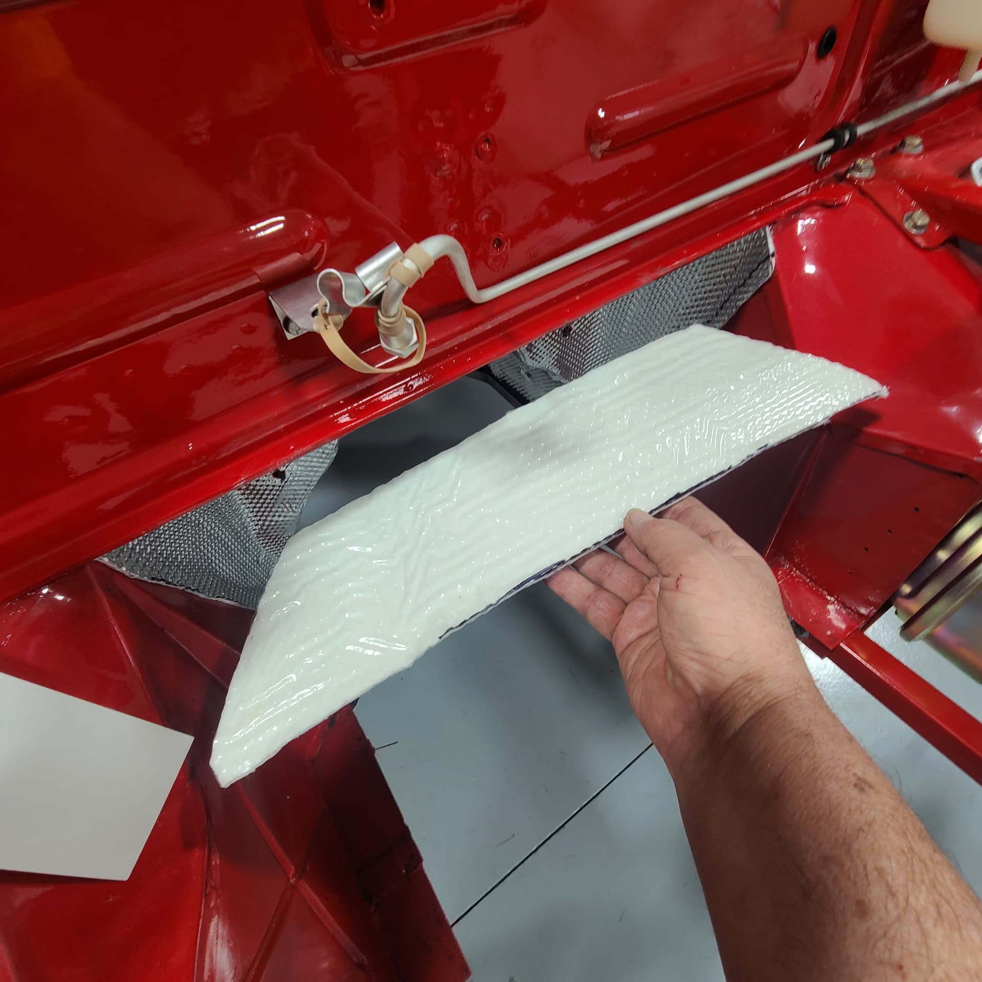
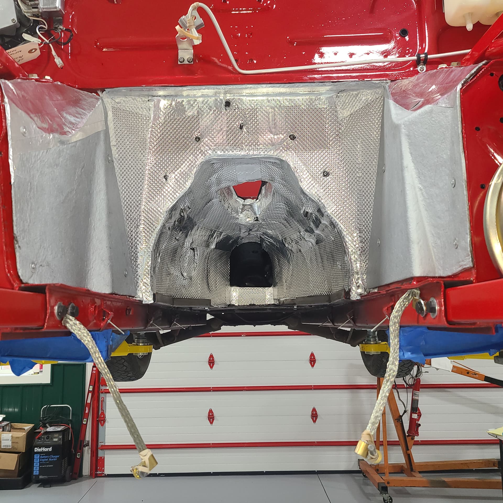
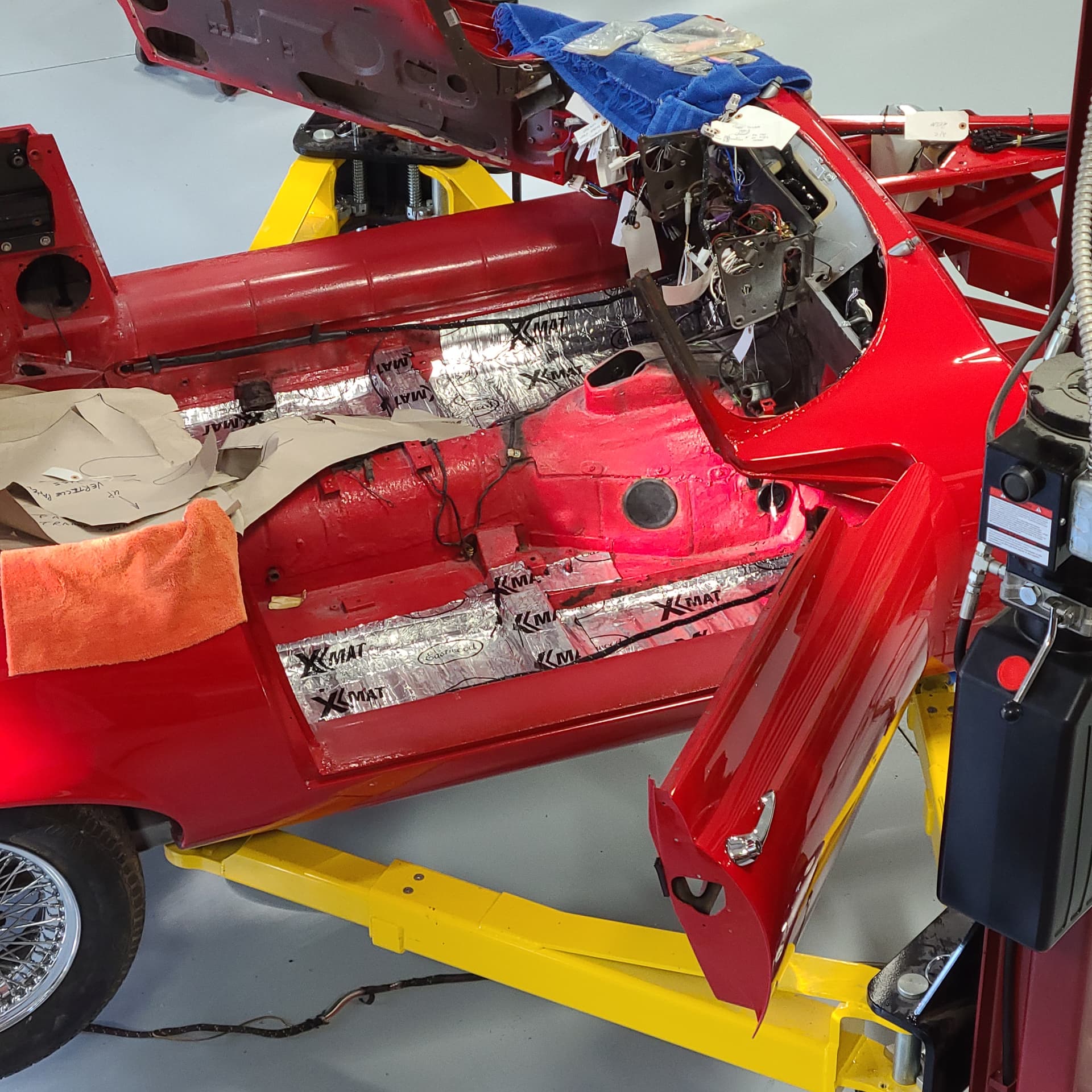
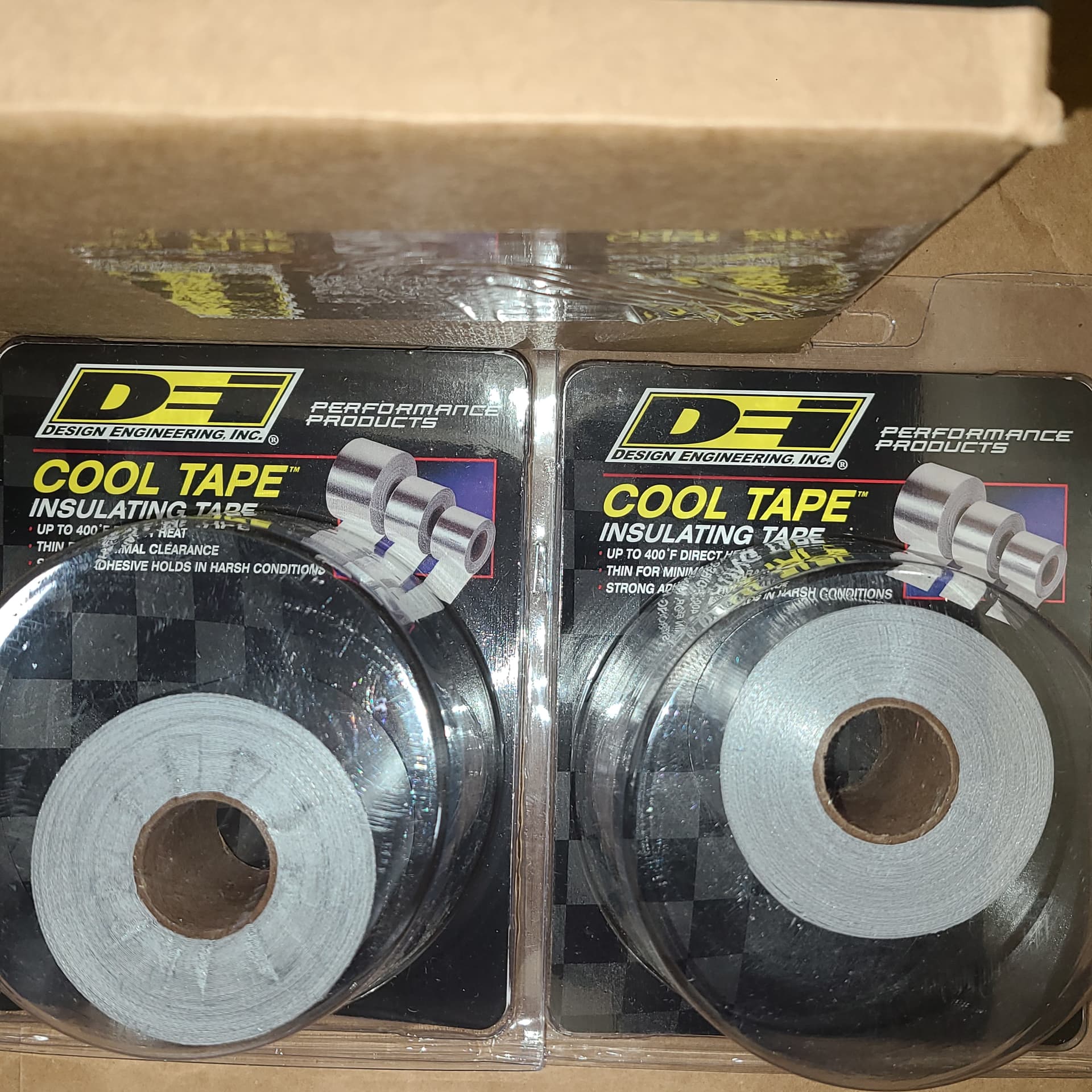
Part VIII - the need for special washers or rivets to attach side chrome on door // testing fuel sender // installing X-Mat sound-heat barrier on floor pan // receive crankshaft and ConRods back from balancing / polishing // the utility of DEI heat shields // return of ½ the front suspension pieces from cad Plater // Interior Kit receives // the complete solution of the placement of unmarked underfelt pieces

Part IX - applying ACF-50 on aluminum pieces, pressing in Front Suspension Bushings, installation technique for C30670 firewall grommet, stripping radiator cowl. dealing with inner and outer seals on window crank handle.

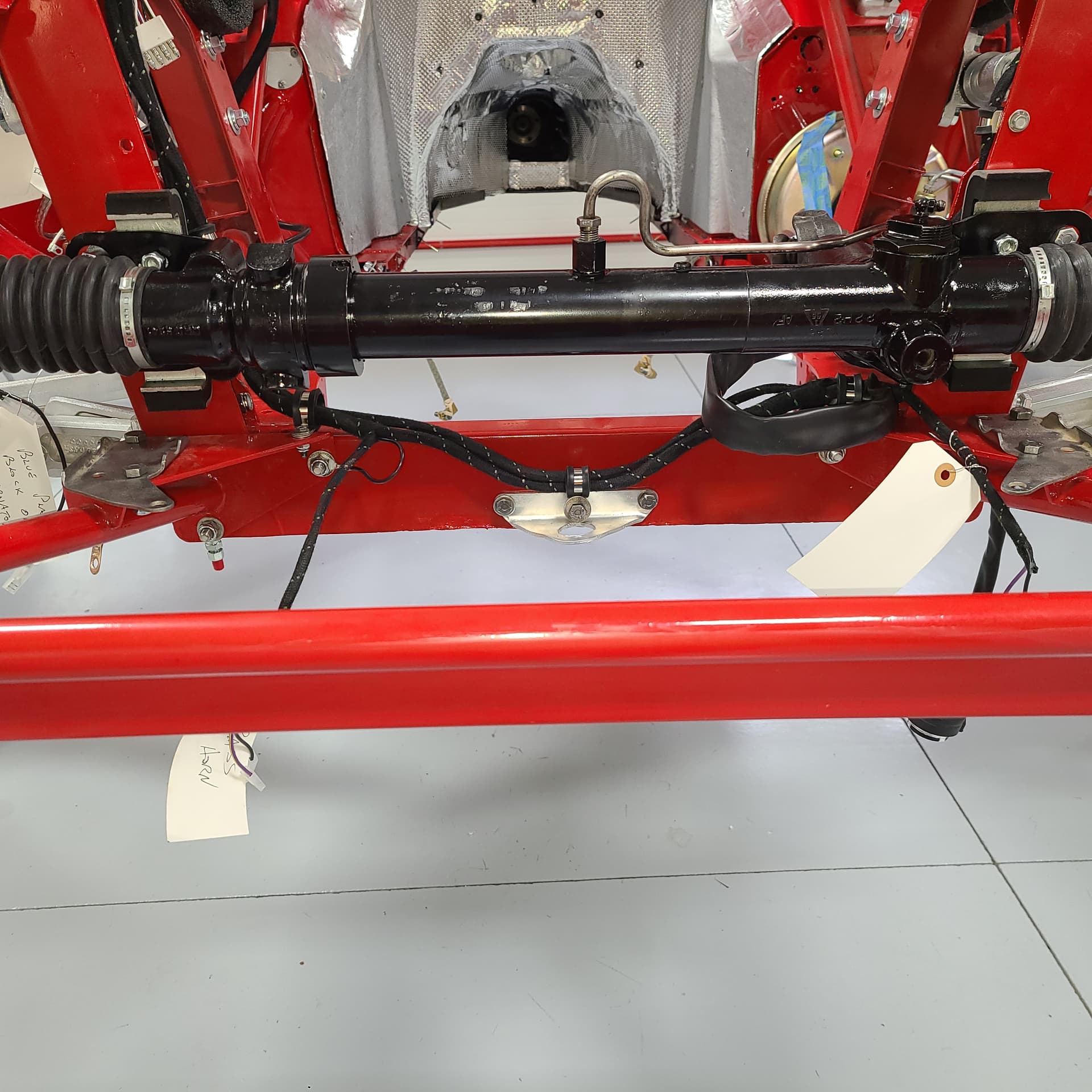
Part X - assembly of Pistons onto Rods, deciphering A and B pistons vs A and B Head on V12, beginning to reattach front suspension, front horseshoe frame can go on two ways but only one is correct, techniques to plug the air Injection Ports on exhaust side of V12 heads, powder coated cam covers, locknuts vs lock washers, repair options for A/C evaporator and condenser, repair options to rebuild PS rack, A/C compressor replacement options, relay on switches of A/C evaporator, window regulator and various door seals, installing pistons on crankshaft, no need to clock gaps in piston rings, correct version of timing chain tensioner, PDWA install, renewing Radiator Fan Motors, and Bulkhead Layout diagram.

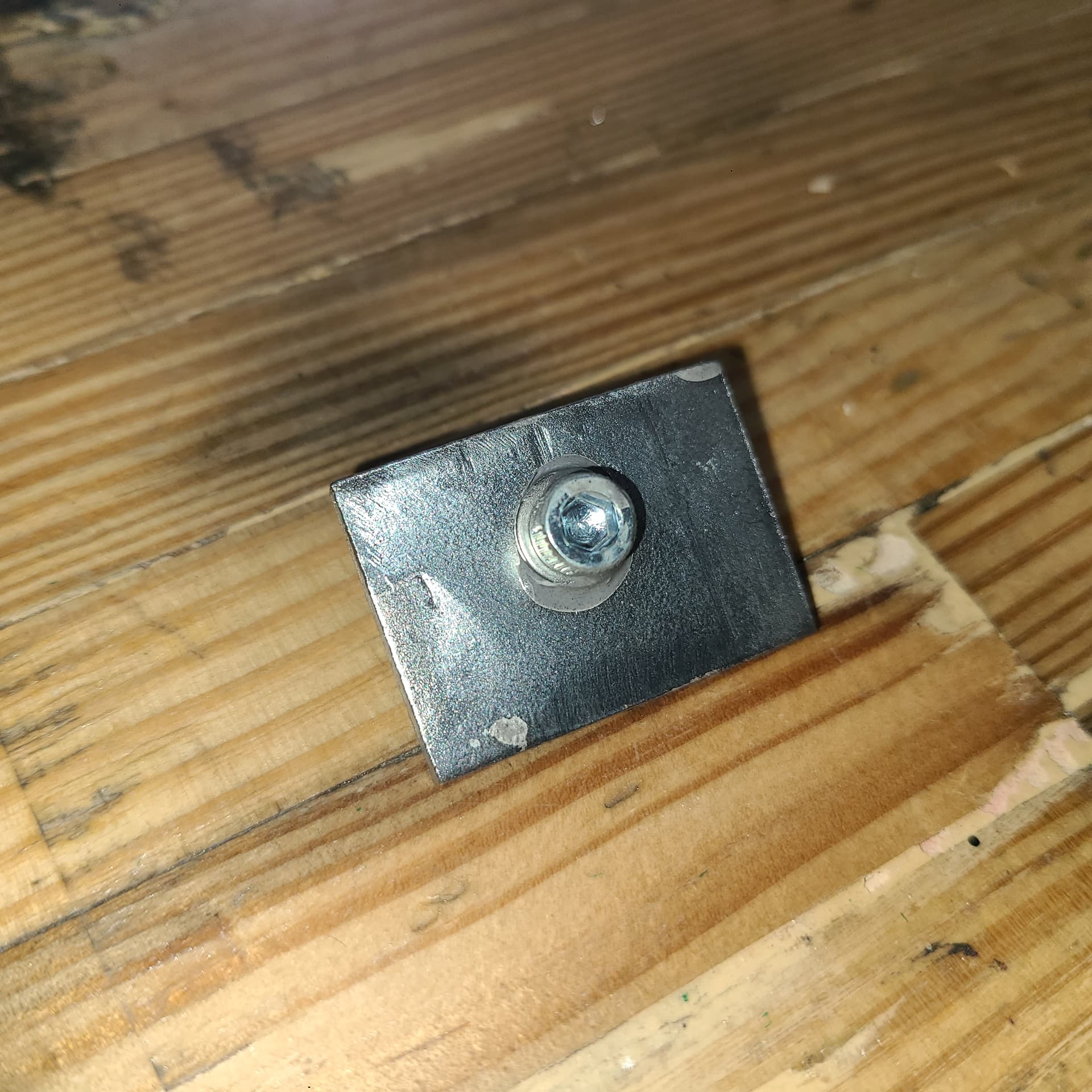
Part XI - how to re-attached hard lines, sources for Belleville Washers, correct assembly order for washers/spacers/etc on upper/lower front suspension, THE definitive discussion about window regulator - where seals go (and where they don’t) - lube points - winder spring - how to insert the regulator - sequence of insertion, Lesson Learned about trusting vs verifying (ref machine shop setting valve lash), dimensions and obstructions for hard wood spacer insert in the bottom of the picture frame, adding a duct fan to fresh air hoses, grounding strap(s), and it’s a tie down point used during shipping not a towing eye.

2 Likes

I usually try to open a new Part of my continuing Thread with good news or a major accomplishment. Not so this time.

I post this as a caution to others restoring a Series III (I assume but don’t know for certain the same mechanisms are in place on earlier E-Types).

Window Stops - there are two. One is on the top of the window frame and the other rests in the bottom of the door casing.

The top door glass stop is simplicity itself.

Is a ~1/4" thick rectangle of steel with a stud offset from the center. I snapped off the stud on one of mine while trying to remove it. After I drilled out the remnants of the stud, I JB Welded a #8 (or was it a #10) bolt thru it. Then I ground down the head so as not to interfere with the movement of the regulator.


/
/
Sorry its out of focus but this better shows the offset position of the stud (or in my case, the threads of the bolt) while JB Weld was drying.

/
/
The stud is bolted to a slot in the top window frame that is angled about 45°. This allows a small bit of adjustment to properly position the stop; the rectangular stop can be pivoted 180° which allows the offset of the stud to be higher/lower in the frame, doubling the available adjustment.

/
/
The bottom edge of the stop is aligned (with shims - this one didn’t needed any) to the interfere with the upward movement of the window frame by preventing it from being raised too high. In this photo you can see how the window stop arrests the edge of the frame holding the glass.

/
/

The lower stop is even more simple and basic. It is a 4-5" length of closed cell foam (it is about .75" x .75" in profile). It was glued inside the bottom of the door casing centered along the length of the regulator.
I can’t lay hands on my one surviving example - so no photo. One of mine is long gone. I had planned to make a replacement (cuz it is NLA) out of an old kneeling pad.
I waited too long.
Clearly these Styrofoam(??) blocks prevented the windows from being lowered too far and kissing the inside face of the curved door casing.

I don’t know when this (minor but now extremely noticeable) damage occurred - I just noticed it yesterday. The inverted dents are small pimples on the lower portion of the door. They are easy to see in the reflection of the paint (once you know they there), but hard to photo:


This is the worst of the two. There are 5x cracks in the paint, each about 1/4" long, radiating from the tip of the pimple
/
/
Not as evident and visible only when I lined up the pimple with the reflection of the power cord of the shop vacuum

Minor - YES
Irritating - MORE THAN A BIT (I was in a blue funk all of yesterday – the day I noticed them)
Repairable - YES. I gotta remove both doors to install the A-Pillar seal. That might be the time to take both doors back the painter for some feathering and repainting.
Economically Repairable - remains to be seen. Gotta wait to see what the painter has to say . . .

2 Likes

I am saying bad words in commiseration with you. People with coupes also face this horrible possibility, if they use the wrong screws to install the rearview mirror.

I’m going to say that the painter will be able to fix those pretty easily, and not for a massive amount of money.

2 Likes

Craig

Sorry to hear about your paint issues, but things are bound to happen in reassembling a car and if we insist on 100% perfection in our work and results we are both going to be unhappy a lot!

Last year when I was organizing my shop to start working on my cars I pulled my 12,000 mile 1983 Mazda RX-7 (my only old non-Jaguar, bought new in 1983) out into the drive. That same day I unhooked my trailer on what seemed like a pretty flat surface and did not block the wheels. A minute or so later I turned around in time to see the trailer rolling backwards directly toward the Mazda and before I could get back and grab it the rear corner made a significant crease in the front fender of the Mazda. After chastising myself for an avoidable error, I moved on and decided to waste no more time and mental energy stewing about it. I will get it fixed and consider it a tax on stupidity.

I am planning on doing my own body work and paint, so your imperfections will likely seem minor by comparison! I have decided that my 74 E Type project will be more about personal satisfaction than concours perfection.

Rod

2 Likes

Thanks Rod –

Good sentiment

I spent more time than I shoulda fitting, applying, and sealing the seams of the DEI Heat Shield I bought for the Transmission Tunnel. OCD kicked in on a whole bunch of work that’ll never be seen except by the guy replacing the clutch.

Photo Story Follows

BEFORE:


There is not any shiny new heat shielding in place in this photo. The aluminum-looking stuff is the naked sheet metal in the tunnel. In addition using gasoline, a heat gun, gasket scrapers and chisels, I wiped down each surface with 70% Isopropyl Alcohol (Thanx @skiracer, for that recommendation) just prior to applying each section of DEI Heat Shielding.
/
/
TEMPLATES

/
/

/
/

A few notes regarding my templates

  • I tried to make a template to fit the entire upward-curved area. Too Hard. It was clumsy enough using stiff construction paper, I would died a slow death trying to apply a sheet of DEI at one go.
  • I made a horizontal seam (note sheets 4 and 6) that followed the join between the gearbox tunnel cover (which I never removed) and the sheet metal in the tunnel
  • I shoulda split the DEI piece that fit inside the gearbox tunnel cover longitudinally. Once I opened the seam down the middle of the DEI piece, it became floppy and hard to control.
  • The seam between pieces 2 and 3 was intentionally offset from the centerline. There is a grommet in the lower firewall to pass wires through that needed to be open
  • I put “See This” on the one piece so I wouldn’t cut it backwards. The rest were obvious as to how it fit - this one is symmetrical.

OBSTACLES


I took the time to NOT cover over the several large rubber body plugs (someone will thank me for that in 35 years’ time). I also notched around or cut open a hole to account for way too many bolts and stuff.

OBSTACLES II
Insulating the gearbox tunnel cover was the toughest part. If I had removed the cover from the body this would have been straight forward.


/
Making this template while standing under my lift (Thank God for it) working above my head took ages. This is the piece that I shoulda done in two pieces (I ultimately split it while it was on the car - I felt a fair-sized air bubble that prevented stickling the shield to the peak of the curve). The real PITA aspect was notching the holes (two on the left and one on the right) for the A/C condensation drain tubes (they look like pitot tubes on an aircraft).

TAPING
This was by far the easiest bit.


Some notes:

  • The longest piece of tape I applied was 5-6" long. Learned my lesson on templates: short is more malleable and easier to handle.
  • The grommet mentioned above is clearly visible above the arc of bolts attaching the gearbox tunnel cover to the body
  • I didn’t tape the long vertical seam at the mouth of the tunnel - there are two factory heat shields that are riveted in place that will cover them

LAST PIECE?
I have fitted the last piece but haven’t applied it yet. Looking for some guidance.

These two photos capture my issue
This shield is applied to the horizontal ledge atop the tunnel opening


/
/

I am not sure of the utility of applying it?
Its edge will be visible in the engine compartment so how do I neatly finish that off? (If I apply it, I still need to trim off ~1/8" or less off the leading edge so it is not visible once attached - metal straight edge and new blade in the box cutter.)

When all is said and done, I used

  • a single sheet + of DEI 50502 (21" x 48"). I bought 2 sheets but only needed the second to cut out Piece 1 (which I may/may not use)
  • most of 1x DEI 010468 (2" x 30’ of insulating tape) - I bought 2
  • about 1/3 of the quart bottle of 70% Isopropyl alcohol - I bought 2
  • my strong shears to make the initial cuts of the heat shield material and then detailed trimming to get the final fit (I think it took an average of 6 fitting to get each piece to fit correctly
  • a roller that came with the X-Mat I bought to insulate the cabin floor
  • 7-9 blades in my utility knife/box cutter - the aluminum facing really does a number of the edge
4 Likes

When you drive this thing in the summer, you will think back finally on every single second that you spent putting that stuff in!

1 Like

I forget the auto insurance company that runs the ad (Hagerty?) but one of their catch slogans is
.
.
.
.

When hours invested . . .
. . . . become miles enjoyed.

1 Like

Just trim off ~1/4" from the front edge so it can’t be seen from the engine compartment. It will help (a little) with keeping the dash electrics cooler.

1 Like

Ya see – this is a totally doable, functional, out-of-sight, and obvious solution.
Thanks Doug
You just witnessed an excellent example of what happens when OCD (I gotta fit this last piece in P-E-R-F-E-C-T-L-Y-) bumps up against the functional (be done with it - just trim out an little extra bit and stick it in place).

2 Likes

This was a very good day.
This was the sort of posting I would have liked to use to open Part XII of my Restoration Thread.

I finally solved the source of my creaky driver’s side window regulator. This is what I had three weeks ago:

It took a coupla light bulbs to come on and a recommendation from my friend Nick who has 40 years invested in working on '58 to '66 T-Birds. His comment: the noise is assuredly coming from the spring; it needs to be cleaned much better. Do NOT reinstall the regulator until it works silently on your bench.

That ignited a few lightbulbs:

  • an earlier video I made showed the regulator working silently without the spring in place.
  • the spring had been cleaned and oiled but still showed signs of surface rust. (*)
  • I had been blasting some parts 2 and 3 times without really getting them clean (the crushed walnuts in my blast cabinet were worn out)
  • I had replaced the lube in the sealed gears but hadn’t applied lube to the coils of the spring

(*) - surface rust imparts a lot of friction

So, I:

  • Soaked the spring in Blaster for 48 hours.
  • Put new Glass Beads in the Blast Cabinet and truly cleaned the spring
  • Lubed the coils of the spring and the plate it sits on

And this is the result

And while installing the regulator for the 11th time I discovered that the pimples in my doors were NOT from regulator being allowed to roll down too far (see second posting above); the damage was not from the absent lower window glass stop. The regulator can not be lowered far enough to cause the damage. It must have occurred when I was fumbling around with my first attempts to install the regulator (with glass included) and the mechanism slipped from my grasp and crashed to the bottom of the door casing. Small solace.

AND - @skiracer - I also took 2.74 minutes to trim 1/4" off the last piece of DEI and unceremoniously stuck it in place. Done.

4 Likes

Craig did the pimple trick myself on the rear door hatch ( set screws too long and with pointed end ) …… fortunately with a lot of patience I tapped and tapped ( with a small plastic tool)to shrink the pimple to a blackhead… and used a fine brush to apply a sealing and top coat of original paint….would have repainted but it’s metallic and not an off the shelf colour …the painter did not do as I had asked and bought sufficient to do only the job ! And none to spare :rage:

I couldn’t stop myself. I did trim ~1/4" off the leading edge.
But, while I was using the last coupla feet of the aluminum tape covering over a few more seams, I looked up at the last DEI piece – I told myself to step away from the car, to put down the tape . . . I have no self-control. I carefully laid the tape right along the underside of the ledge.

I also riveted the factory heat shields in place on the ends of the opening of the transmission tunnel – kinda finishes off all my efforts with the DEI stuff.

PS - @Wiggles – I also attached a pair of grounding straps (that’s 4 and counting) that I will connect to either a pair of oil pan bolts or a pair of bell housing .bolts
.

3 Likes

I stumbled on this little gem and my OCD antennae went into over-drive.
The good stuff starts at 2:30

PUT - - - - - THE - - - - - WALLET - - - - - DOWN

BUT; - - but . . . nearly all my wiring is clean and easily accessible.
MUST - - MARK - - ALL - - WIRES

This model has been superseded by the Brady M210

2 Likes

Regarding the heatshield work, you could improve on this by having an access hatch cut in low down at the very front of the gearbox tunnel cover piece. This will give you access to bleed the clutch slave cylinder (if you have a manual transmission) from the driver’s seat, rather than having to reach up from underneath the car.

The original heatshield was an asbestos material and therefore an insulator. There is no reason not to reuse it if you simply spray it with a sealant coat of paint. The carpet underlay was also an insulator - a jute material.
By contrast, the new material you are using doesn’t look like an insulator - it appears to be a corrugated aluminium sheet. I would have thought that it will just heat up and dissipate heat rather than insulate the cabin from engine heat. Are you sure it is a good material for the application? Presumably it has an insulating backing of some sort?

kind regards
Marek

2 Likes

It’s this:

1 Like

Thanx for all your input and comments - I think I have a pretty good solution in hand:

Pretty sure the Series III came with that access in place (actually, two of them) both on the passenger side where the slave cylinder sits on a Series III:

Hard to see in this photo, but between the top two “X-mat” logos on the transmission tunnel I cut out a hole and labeled “Large Tranny Plug”

I did just that - I sprayed the original shields with several coats of this stuff (the replacement weighed 3.5lbs each made of 1/4" thick aluminum and would have served as radiators - the original asbestos material was 0.5lbs )


I also reinforced some of the shields that had thinner areas from wear with this

I used this DEI material based on having seen other J-Lers use it (looks like @skiracer and @Wiggles were quicker on the key board) and this, quoted from their web-site:
Floor & Tunnel Shield II™ solves the problem of needing a high heat barrier to block heat from any source intruding into interiors and damaging components and electronics.

Use as a barrier to reflect and insulate from any heat source. Designed to provide the best possible heat protection in areas where high temperatures are always present and problematic, Floor & Tunnel Shield II limits heat transfer on fire walls, transmission tunnels, floor boards, fuel cells and other areas where heat is an issue.
Floor & Tunnel Shield II provides excellent light weight thermal protection, acts as a guard against track and road debris, and provides sound deadening as well. Constructed with an embossed 10 mil aluminum face bonded to 1/8″ composite glass-fiber core and backed with a high temp super strong pressure sensitive backing, Floor & Tunnel Shield II withstands up to 1750°F. The adhesive side holds past 450°F. Its improved multifaceted modern aluminum surface offers improved reflection and rigidity and allows for ease of installation – aluminum side must face the heat source. At only 3/16″ thick, this product can be shaped and trimmed for a custom fit and is ideal for minimal clearance areas. With a unique and patented finely woven glass-fiber backing, Floor & Tunnel Shield II is the easiest, most cost effective way to control thermal transfer while protecting expensive components and vehicle occupants from extreme heat situations and sound. Floor & Tunnel Shield II can be used on any number of surfaces including, metal, aluminum, carbon fiber, plastic, and more. Multiple uses include: fire walls, under hoods, transmission tunnels, floor pans, fuel cells, and exterior under vehicle locations – anywhere to reflect damaging heat.

https://deipowersports.com/products/extreme-heat-barrier-21-x-48/

2 Likes

I used a very similar product to this on the Jeepster, and it greatly helped lower the temperature around my feet.

Today was a day of test fitting. Most of my time (and I will NOT divulge how long it took) was figuring out the mounting arrangement of the PS Rack. Nothing is bolted in firmly - just making sure I know/remember how it fits backs together. I have two dozen items that I’m gonna powder coat and some of them are amongst the PS fitments.

This brings up a few questions that the pros will need to answer.

(FLASH BACK - some of you have twigged to the fact that when @Wiggles makes his near-monthly pilgrimage south, I have a handful of while-you’re-here-and-sober questions. Last visit I had stored up 5-7; few months back it took Paul over 45 minutes to scratch all my itches.)

BACKGROUND - It was on one of tutoring tours of my shop that Paul noted a crease in one of my 11-13 brake lines (not a cut through the metal). It was enough to immediately catch his eye; when I mentioned that I was 95% sure they all originals, he counseled replacement of the lot.

QUESTION 1 - while test fitting the PS Rack, I noted one of the steel lines on it has a dimple in it. It’s not as bad as the nick on the original brake line but I did recall his admonishment. So - they are good to go OR time to replace one or both:


/
/

This one looks like something was dropped on the line or it had a collision with something hard while the engine was being being installed or removed . . .
/
/

. . . while this one has a slighter blemish on the inside radius of a slight bend in the line

QUESTION 2 - One the topic of PS Racks, this is how the lines were installed on my rack when I removed it - note they cross each other. I have found two photos on-line copying this configuration.


/
But I also found this photo where the two lines sorta parallel each.

Now I realize this will be driven by how the lines align with the ports on the under-side of the pinion housing, BUT only one can correct. What gives??

QUESTION 3 - once the PS Rack was in place I noticed there was precious little space to fit the sway bar under it (I haven’t tried that yet - it is pretty close). I suspect that no matter which I install first, it’ll be a cast-iron b!tch to fit the other. But - is one sequence batter than the other or is it a tight squeeze regardless of the order of installation?
COMMENT - I am stalling the Team CJ H/D Sway Bar which has an OD of 1-1/8" vice the 0.9" original.


/
/

/
/

Isn’t it easier to install the engine without the power steering rack installed? :slight_smile: