Today (17MAY23) I received an email from Jonathan at Used Original Jaguar Parts & NOS Parts (*). He has a pretty impressive sale (35% off) going on from now until Sunday 21MAY23 on used parts. Heavy representation of Series I and 1 1/2 parts. Some Series 2; a coupla Series III.
Simply from reading various postings here, these parts appear to be hard to find but always sought
pg 5X - Original Horn Button
pg 63 - Demister Vent Y pieces
pg 63 - Demister Vent delta pieces
pg 68 - Horn Push Rods
pg 68 - Horn Push Rod Kit
pg 113 - S1 3.8 Gear Lever Metal Gauntlet Cover
pg 114 - LUCAS 33285 6RA Starter Relay Dated 3/67
pg 114 - Early E-TYPE S1 3.8 alloy Gauntlet Cover and Chrome Trim
pg 115 - S1.5 & S2 E-TYPE Radiator Bracket Set
pg 129 - S1 E-TYPE Bonnet Headlight Lens Stone Guard Set
I’m on age 90 (12 parts per page) and counting
(*) - isn’t this the guy who bought out John Ferrell’s inventory??
I think I did a step by step in my original post but, yes, the angle was good for me. I did, however, put it in a vice and crushed the kink out of the base to make it straight. Might need to touch up the paint after. The bottom of the mount hits the floor and gave me the correct angle for the pedal. I found it best an inch or so further back than the clutch pedal. Two screws, very sturdy.
Hello Craig,
Is the above diameter of the Minor Diameter pressed in to the Dowel? I can’t see how that can be when you have an 8.27mm Minor Diameter pressed into the Dowel.
Hello Craig,
A part of your Steering Column assembly that is worth looking at before its installed, is the Brass Horn Contact Sleeve, circa half way down the inner shaft. A copper pickup finger runs on this and more often than not, part of the Brass Contact Sleeve will be worn through to the insulation sleeve between the bore of the Contact Sleeve and the OD of the Inner Shaft, resulting in the Horn not working when the Steering Shaft is in a position that puts the Copper Pickup Finger in contact with the insulation sleeve.
The part number for the repair kit from SNGB for a Series 3 E Type is SBS1279, however, the parts in this kit do not fit. The first picture below shows the profoundly oversize fit of the Insulation and Contact Sleeve is with the Steering Shaft (both should be an interference fit with the shaft)
The following picture shows that the Contact Sleeve won’t fit inside the Outer Steering Column. The Contact Sleeve should be a massive clearance fit inside the Outer Steering Column.
The next kit I was sent is part number SBS1280. This also is an incorrect kit for an S3 E Type, being profoundly too small, and is meant for an S1 E Type and various other Jaguar Model. It seems that there is no kit available for the S3 cars, as the only kits SNGB have don’t fit and despite a few emails asking whether one will be available, this questions remains unanswered.
By “at ~mid-point of threads” in the caption, I mean that I placed the coarse threads of the stud against the dowel and the 9.43mm diameter of the dowel falls ~mid-point of the length of the threads on the stud.
My take from this bad news is that I need to look at the Brass Horn Contact Sleeve. If mine has worn through, is it a simple matter of rotating the sleeve so a new area of it is under the Copper Pickup Finger?
PS - when parked (famous last words) in 1989, the horns worked fine.
Hello Craig,
Not really, to the rotating of the sleeve question, for there are circumstances when you need to rotate the Steering Wheel more than part of 360 degrees and sometimes more than 360 degrees. And who knows at what moment you may need to use the horn? When restoring a car, I believe one should strive to have all features working as they should.
Hello Craig,
So I take it that you haven’t screwed the Dowel in more than the Thread impression that measures 8.27mm. That being so, I would machine the end of the Dowel down to say, 8.5mm for the length of the Thread on the Stud and screw that into the thread in the block. However, if only a part of the first thread helix exists, it will still show as an impression on the amount of the Dowel that you screw in. You have to follow up with something like a length of welding wire, with a bend at 90 degrees at the end that will fit in the threaded hole, say a 4mm length bend, then use that to feel if there are viable threads further down from the top of the block.
If you get a good impression for the length of the Thread, machine another length to take an impression to a diameter midway between the Major and Minor diameter of the Thread and screw that in to the Block. If the Thread is reasonable, you will get a fairly good looking formed thread on the dowel.
Based on what you’ve shown coming out of the Threaded hole, I would expect the Thread to be Stripped, or that there is a Thread Rescue Insert, or the remains thereof, in there.
Finally got back to things that matter.
I ended up having to make a third dowel to get the proper dimensions.
Without access to a lathe (using a hand-held cordless drill, some sandpaper and a welding glove) I got pretty close to the 8.5mm target.
This is the result of my first effort to gain am impression of the what the threads like look at the bottom of the questionable stud hole (22MAY23).
Definition of Points A thru D on photo 1
A = depth of threads on dowel
B = mid-point along dowel / along threads on stud
C = first (faint) impression threads on dowel
D = tip of dowel / ie - bottom of stud hole
. . . and measuring from the tip of the dowel to the faintest impressions of the threads on dowel = 7.51mm (about 1/3 of the way into the bottom of the stud hole.
Threading the dowel into the stud hole became quite difficult to get this depth. I feared forcing it any more for fear of snapping off the dowel in the hole.
(Trivia Measurement - the replacement stud has an overall length of 130mm
It is now the morning of 23MAY23. I’m gonna apply more oil to the tip of the dowel and see if I can get an impression if the threads beyond those I got yesterday.
I know I have passed the target post length of ~100 posts, but I wanna close out my efforts with @angelw to get a good reading of what the threads look like
Hello Craig,
As I mentioned in an earlier Post, if using the type of wood you have as a dowel, makes it hard to screw into the hole, make one out of Balsa Wood. Although classified as a Hard Wood it is very soft and will take an impression easily.
Hello Marco,
Yes, if the dowel is too tight in the Threaded Hole, but a dowel made out of Balsa Wood normally takes an impression without too much effort required to screw it into the Threaded Hole.
Since you have excess balsa dowels, I recommend you do a test on one to see how much torque it can handle before you try the live version in the block. We don’t need to read a post asking for advice on balsa extraction from an aluminum block.
One idea I thought of is simply to use an actual head stud, coat the threads with anti-sieze, run it into the hold and then remove it. The thought is that the anti-sieze would read the thread depth like a dipstick? Ok, now the pros can tell my why that is a dumb idea and I won’t be offended.
I still have work to do. The new matrix and/or the new the seal still aren’t seated properly. I am considering the option of
(1) expecting the mounting legs (one of which was tweaked during assembly) to close the gap once mounted on the firewall;
(2) drilling a hole for another small sheet metal screw to secure that corner;
(3) disassembling the whole thing (again) and trimming more of the foam seal off the top and/or the bottom of the matrix.
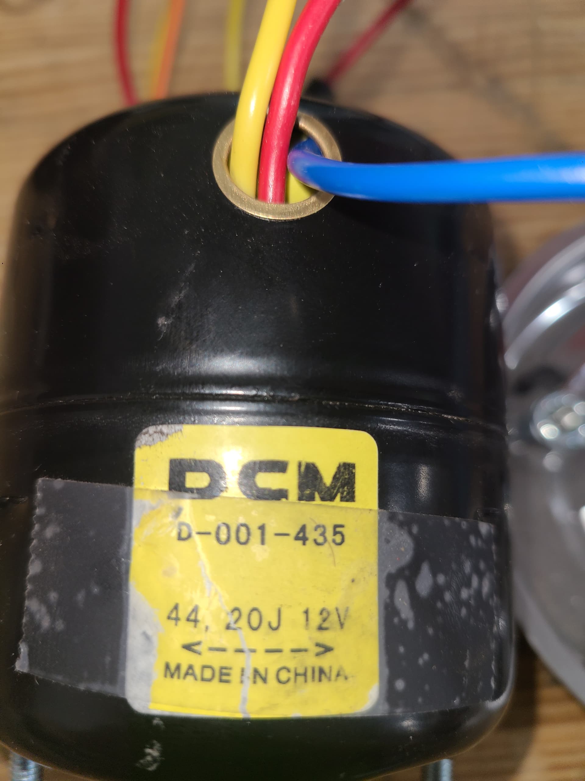
Meanwhile - I just noticed another issue. The fan motor.
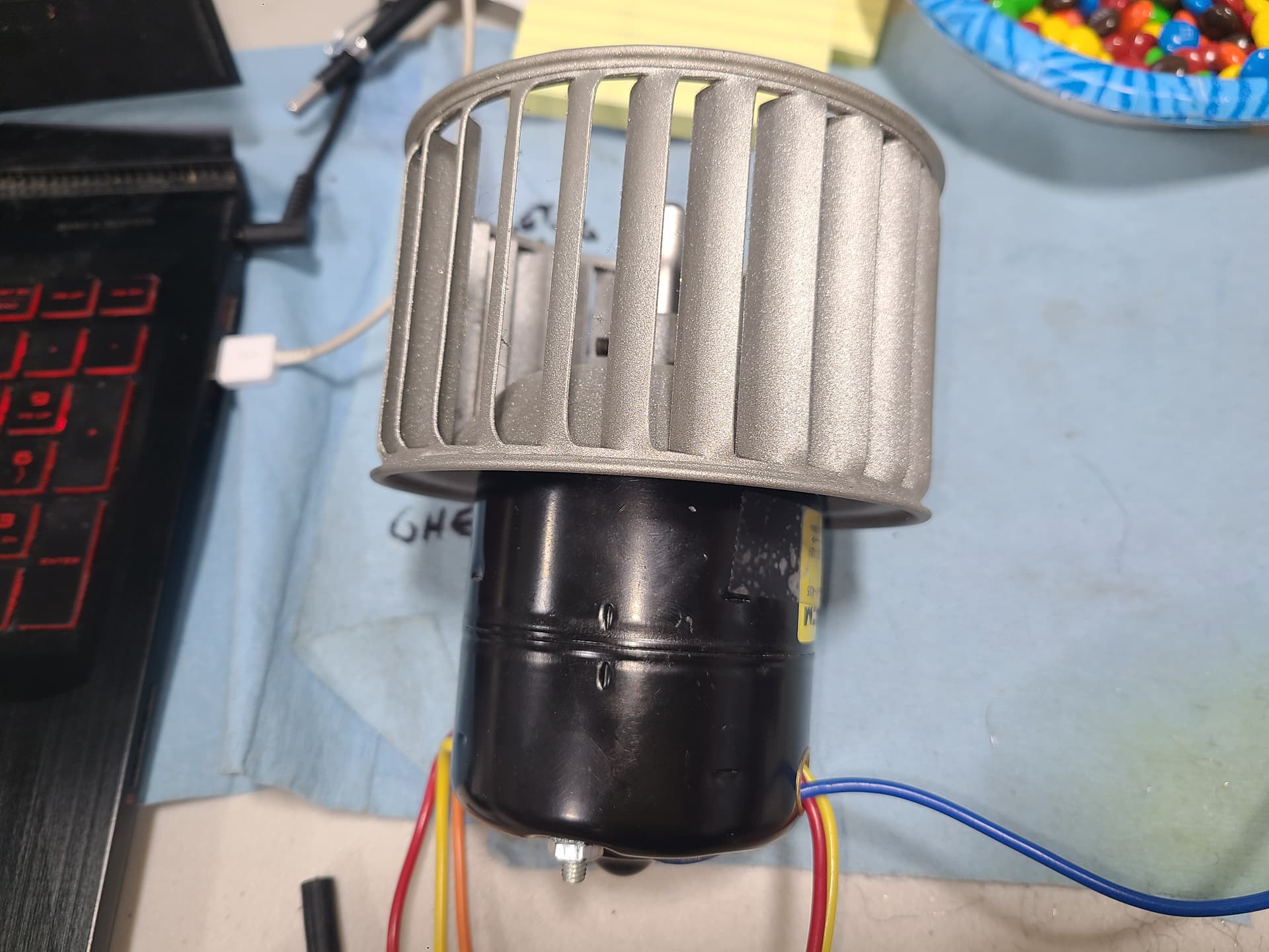
This is the original fan motor and mounting flange beside the new fan motor. I don’t remember which thread it was nor how long ago, but I ordered this fan motor based on a Lister using it on his Jag
The old motor has a diameter of 76mm while the new one is 75.88mm - I can’t imagine that slight difference mattering.
The original squirrel cage fan fits on the spindle; the new spindle has a flat btu I can align the curve of it with the grub screw
Is it just a matter of swamping the bottom half of the fan motor bodies so the new motor has the mounting tabs? Looks like I may also need to trim the length of the through-bolts or maybe use the original bolts on the Frankenstein motor.