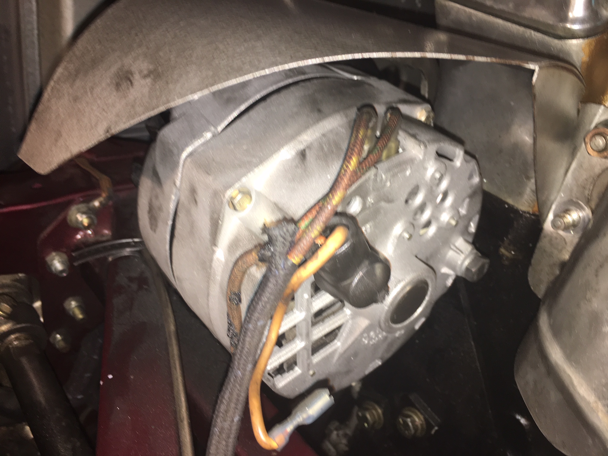
This 64 E Type (in Dallas) has a ClassicJaguar alternator conversion kit (using a two wire Delcon alternator) ,I installed (California) years ago. My son just had the alternator rebuilt after inadvertently reversing battery polarity, and now it is showing 16 volts and is leaking water from the battery.
I have no data nor diagrams with me. Can someon please validate or offer corrections to the wiring connections which I think suspect are incorrect? I seem to recall only two wires were used. The wiring harness is a stock 64 harness for a generator system.
Thanks, Mike Moore


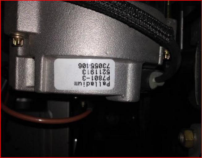
Not sure that this is going to help much if at all Michael but I got a replacement from CJ a couple of years ago, here’s some pics…


Mike,
Terminal 1 goes to the idiot light. Terminal 2 is the sense line, which should go to battery +, ideally directly on the battery. Outputting 16V indicates either the sense line is not connected, or the regulator is toast. The S10 is the simplest alternator in the world to rebuild. A complete kit of ALL necessary parts (regulator, brushes, bearings, etc.) is available for under $60, and doing the rebuild takes about 20 minutes, the only special “tool” needed being a paper clip to hold the brushes back when the housing is assembled.
Regards,
Ray L.
1 Like
Assuming the wire to terminal 2 is connected to the battery, it could also be that there is a voltage drop on that wire. Thus if the battery were at , say 14 volts, but with a voltage drop of 2 volts, the alternator will try to increase its out put to achieve 14 volts at terminal 2. But, because of the voltage drop, the battery actually now has 16 v there. In other words, with a volt meter, confirm terminal 2 is the same as battery positive before you condemn the alternator.
Tom
The sense wire carries near ZERO current (micro-amps), so a voltage drop across that wire is virtually impossible. But, if it is (incorrectly) connected to a point that is NOT directly, and well, connected to battery +, that is another matter. The simplest test is to short terminal 1 to the output terminal, and see if the output voltage changes. If it does not, then the regulator is toast for sure.
Regards,
Ray L.
I had a similar.issue with 15.6 volts and sensor wire attached. It maybe that you dont have your ign light properly wired or the bulb is dead. Bosch confirmed that requirement! during my rewiring i put in a bulb in the ign light socket but didnt have the wiring to the alternator correct. You should put a 330 ohm resistor across the bulb in case the bulb burns out, also recommended. email me with your address and I’ll send you a 330 ohm resistor. I had to buy 25.
Ray, Tom, Mike and all, Thanks for all the help. The sensor we have is a voltmeter, not a light (although I now wonder if there is also a red light which comes on when it isn’t charging.
I did run across this diagram on-line allegedly for the Delco alternator.

Mike,
If I am correctly reading your diagram, and it is wired as you indicate, then it is wired incorrectly. The two pin connector, when viewed from the rear of the alternator, has Pin 1 on the left, Pin 2 on the right. The numbers are normally cast directly into the alternator housing.
Pin 1 is the idiot light terminal, which should go either to the Ignition light in the speedo, or to a small resistor (220 ohms or so, value not critical) to switched +12V. You show it being connected to the output terminal, which is wrong, and will very likely damage the regulator.
Pin 2 is the sense terminal, which should be connected AS CLOSE AS POSSIBLE THROUGH A DEDICATED WIRE to the battery + terminal. It can be connected directly to the output terminal, but that will NOT provide optimum regulation. You show it going to a voltmeter, which makes no sense at all, and can easily provide the regulator with a false voltage reading, causing poor, or no regulation.
Have Barry disconnect the 2-pin connector, and rig a jumper wire from Pin2 to the output terminal, and see what happens. My guess is it still will not work, which indicates the alternator is fried. A replacement is available from absolutely ANY auto parts store in the country, typically for $30-60. They may not have one in stock which has the housing mounting ears properly “clocked” to match the old one, but that is easily corrected by simply removing the four screws that fasten the two housing halves to each other, rotating the rear case to the position needed, then re-installing the screws.
Regards,
Ray L.
To add to Ray’s information, terminal 1 has two functions. It can go to an indictor light. It must be switched off when the engine is not running, or it will drain the battery. But it also must be connected to a voltage (need not be full 12 v) on start up to excite the rotor to get the alternator charging. It need only be connected for a split second. Sometimes, there will be enough residual magnetism in the alternator that this connection may not “have” to be made, but it always should be. So, to test the alternator, 12 volts should be connected to BOTH terminals 1 and 2 (not just 2) to see if it will charge, but just for a test (as terminal 1 needs to be switch off as said above.) Connecting 1 to the output will not harm it. Terminal 1 and the output terminals are actually “similar” posts internally. Terminal 1 simply leaves the diode trio rather than the main power diodes.
Tom
Thank You Tom. Does the diagram I posted look right to you?
Mike Moore
i been reading this thread , sounds like a may have the same problem?
different alternator tho!
Mitsubishi NEW not rebuilt, has same single output terminal, and a two wire plug, supposedly #1 goes to light , #2 for sensing + from key on position hot lead!
but charging 16.2 volts at the battery, NEW belt sqeuking loud wore out in 15m minutes, seems a super load is on alternator!
any IDEAS?
put a momentary button in sensor lead , no charge at all, a slight push of button and things seem OK , but if i hold button for 2/3 seconds , alternator goes NUTS, sqeuikin squawkin?
ron
Tom,
I have never seen any documentation even suggesting a connection to terminal 1 is required on a 10S1. The 10S1 has an internal field diode trio to energize the field, and there will ALWAYS be plenty of residual magnetism to bootstrap the field on start-up. The idiot light current path is only required on older alternators, like the Lucas, which do NOT have a field diode trio.
Regards,
Ray L.
ALSO, it is recommended that the battery be charged before running the new alternator (note attached to my new Bosch alternator from Bosch).
We’re dealing with a Delco here…
Regards,
Ray L.
Ray, attached is some information from a training manual published by Delco Remy. In particular, start at paragraph 4 where it describes how the alternator initially starts with battery voltage, and then paragraph 7 where if first confirms the connection, then describes how the diode trio takes over.
Due to this, if the indicator light bulb is burnt out, the alternator may not charge. The first step to trouble shoot this system is to always check that the bulb lights, key on, engine off. Many alternators have been replaced due to not first checking that the bulb lights first.
Tom


that is why you out a 330 ohm resistor across the bulb socket, just in case the bulb burns out
Published in what year? I see no field diode trio in any of those diagrams. The early 10S1s did not have them. At this point, you’d have a hard time finding one not only with the trio, but setup for one-wire operation. Those only need to be energized one time (using the hole in the case for that purpose), and they will self-excite from then on.
Regards,
Ray L.
Per the back cover, I believe it was published 3/1/75. Here is the next page, I guess I should have included it the first time, sorry.
Tom

Here is some additional information from Delco Remy. Note in particular page 2, operating principals, the current through the indicator lamp, and page 8, testing the alternator. They state to connect 12 volts to terminal 2- as you stated, but they also state to connect a wire to terminal 1, through a 10 ohm resistor. I have found no resistor, or a higher resistor works for me, but the 10 ohm is similar to an indicator bulb. (I also find it interesting Delco always called their alternators by the name generator, but the rest of us typically never do.)
Tom
Delco 10SI 1g-266.pdf (1.2 MB)