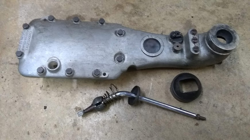
Here is the box in 2 1/2ltr 80034.!
I believe I have some numbers stamped around the Welsh plug but do’nt hav a photo at present.
IMG_1513|375x500


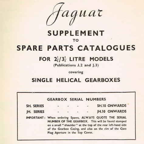
For Art, no I don’t think I suggested the date of '46 anywhere, in fact the parts catalogue supplement for the single helical gearboxes is dated 31st January 1948, and the single helical boxes are mentioned in Service Bulletin 28 dated June 1948 as being in current production, so it seems likely that the SH (for Single Helical) and JH (Jaguar Helical) boxes came in around that time or a little before.
Just guessing, but the task of ordering parts became more complicated, and that could be the reason they decided to start giving them intelligible serial numbers, beginning with SH10 and JH10.
SB28 mentions that the serial number was given on a plate fitted alongside the commission plate.

For Graham, wow you have a lot of numbers on yours. SGDG could be something like Standard Gear Drawing 787432. Mine has nothing but the mostly illegible cast numbers and the 1549 at the Welch plug.
No Art,
It looks as if they came in for the 2.5 litre at chassis number 510881 which has engine number P899 and that was some time in 1947. In the 3.5 litre it was chassis number 612041 and I don’t know the engine number. Just as a matter of interest Art, does your gearbox have the older style top cover with the ball pivot for the lever and is your lever bent backwards like Rob’s?
Peter
Rob/Peter
I wouldn’t put to much credence into when Jaguar say they changed numbers. My engine S1515 is supposed to have automatic ignition advance according to the workshop manual (I can’t lay hands on the manual to quote the change number but it’s a good number out)
Yes I have the ball shifter. I’ve attached a picture.

Art
Hello Art,
Is your gear lever angled backwards at 45 degrees like Rob’s?
Peter
I just noticed, the 2.5 and 3.5 parts books show a bent shift lever. No change in part number, 41359 or C879. Maybe it was one of those “silent changes”.
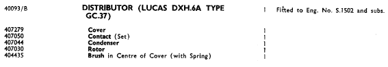
Looks like the automatic advance distributor was supposed to come in at engine S1502.

Talking of drafting mistakes, Service Bulletin 64 dated April 1950 draws attention to an error in the Plate showing gears in the single helical boxes, the 3rd/4th operating sleeve Item 21 being drawn backwards. They were concerned that a service operator might assemble it wrong.
Peter,
The angle is about 10 degrees from vertical.
Rob,
It would be interesting to know how many engines beyond my engine S1515 that have the manual advance. Actually when you think about it, how many engines were produced in a day?They probably fitted manual advance until the shift change then the subsequent shifts were fitting the
automatic distributors.
Art
Thanks Art, That’s interesting to know.
Peter
My shifter is about 45 degrees.
Using this chart of car production figures, deleting the 1.5 engines that still came from Standard, and assuming a 5 day work week and 52 weeks a year, an estimate for '47 & '48 comes out to about 9 or 10 engines per day.
There was probably some foreman or clerk responsible for recording the serial numbers at which changes in specification occurred.
My new counter shaft and needle bearings arrived Tuesday, and the new shaft C1856 is a match for the old shaft, which I am tentatively identifying as C915 or 48756. Same .980" OD and 11-1/8" length, same tail end slots and flat spots. The only difference I can find is the bore of the oil passage is slightly smaller on the new one. Perhaps that was the reason for changing the part number, or perhaps there was an improved steel or something. Anyway it is a good interchange.
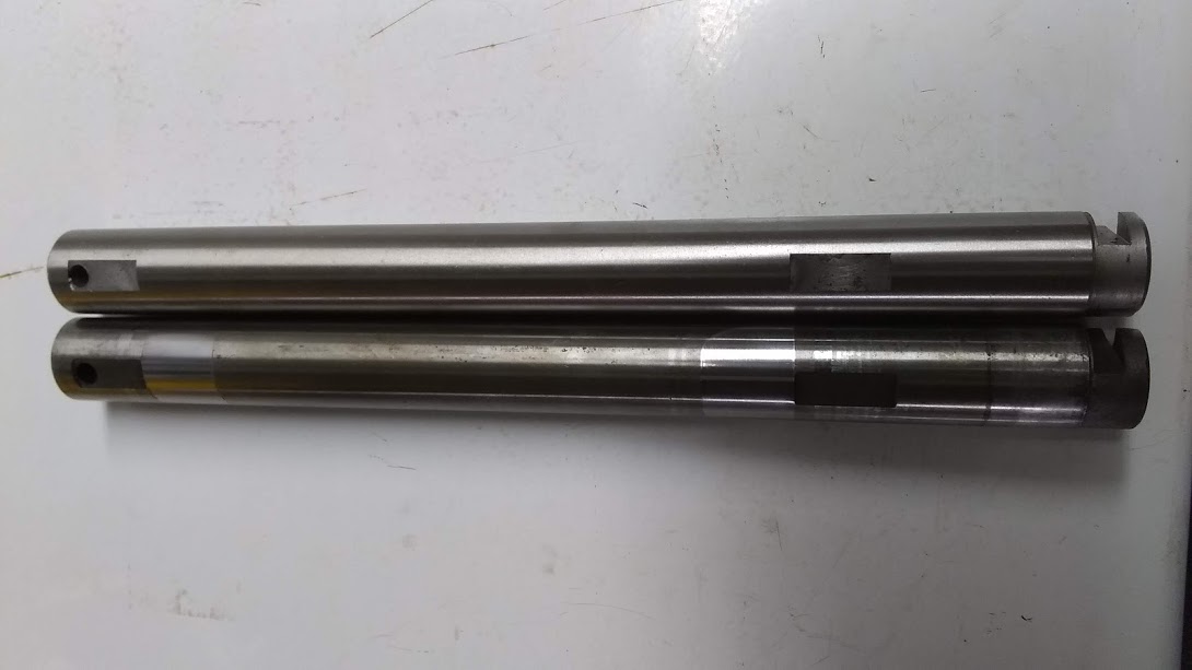
The new C38573 needle roller bearings are the same .118" diameter and .930" length as the old C918 rollers, the only difference I can see being the old ones have perfectly spherical ends, where the new ones have flat ends with .050" radii. So also a good interchange.
I made a dummy dowel .975" dia x 7-9/16" long.
That’s all good news Rob.
Peter
The gearbox is back together.
Here are some assembly notes for those who may follow.
A very important tool is the .975" diameter dummy counter shaft, made to just fit with a small 1/32" clearance down in the main case between the holes where the counter shaft fits through.
- Don’t forget to put reverse gear in first.
- I tried to follow the normal practice with single helicals where you set the counter shaft assembly down in the bottom, then put in the main shaft and input shaft with their bearings in place, then lift up the counter shaft to it.
Nope, not on the double helical, I had a terrible time with those double helical gears sliding around on the counter shaft and could not get them to mesh all at the same time with the main shaft. - The main shaft front and rear main bearings are not a single assembly; the rollers and inner ring are separate from the outer ring. Possibly Moss had a good reason. So I set the counter shaft down in the bottom. Then put in the main shaft and input shaft WITHOUT their outer bearings. This allowed the main shaft to move upwards. So I turned the box upside down. Then I could get the counter shaft in place where I could put in the real counter shaft, which pushes the dummy out the front. Turned the box back upright and I could get all those gears meshed. It might have been even easier with the inner bearings off, and may have been Moss’s method.
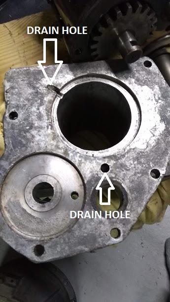
- Then put in the main outer bearing rings. The front cover flange has a drain hole which goes at the bottom. I used the gentle double hammer method. Check rotatability, if it binds, tap around the case and side taps on the input shaft.
- I made paper gaskets for all face joints, and smeared a thin layer of Permatex Ultra Black Gasket Maker on both sides. Be careful not to get any near the drain holes.
Also on the counter shaft front plug disc.
- Put on the tail case without its rear ball bearing. The reverse gear shaft has no oil seal, so I think there is a potential oil leak around it. I smeared some gasket maker around both it and the counter shaft, and the rectangular keeper and screw.
- Don’t forget the spacer tube, then put on the tail bearing, again gentle double hammers. Check rotatability again.
- There is a spacer about 1/8" thick between the bearing and the speedometer gear, and the speedometer gear has a boss on the forward side. Check the gear is in line with the hole in the tail cover. One of the five screws is short and goes in by the speedometer drive. Turn the box up so you don’t drop that screw inside where it doesn’t belong.
- Rear flange on with a flat washer and nut, tighten just enough so you know the flange has gone in as far as it will, then back off to the first slot in line with the split cotter pin hole. New cotter pin of course, why be penny wise and pound foolish. Check rotatability again.
- Put in the speedometer drive gear last, check rotation. This may be another potential oil leak, so I smeared gasket maker around it and in the rear screw access hole.


Touch up the paint.
Hopeful of success, but I won’t know until next spring.

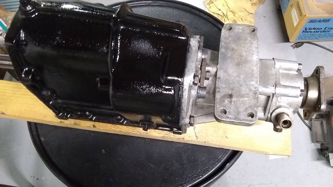
Cleaning the pale green paint splatters off the bell housing, I noticed it is stamped on the left side:
TESTED A and M.G.C which is presumably Moss Gear Co., and also SS and 39(?) and perhaps some other numbers now destroyed by someone’s hammer.

Art, cars fitted with vacuum advance distributors had different carnies with a take off for the vac tube.
Great job on the gearbox reassembly description with excellent photos Rob.
Well done!
Peter
I’m guessing I know why Nu. 1 is Nu. 1…
Excellent write-up.
Hi Rob, just a question relating to your nice and clearly detailed instructions. In item 9, you note to tighten the flange nut just enough to confirm the flange has seated to the bearing, then back off the nut to match the next split pin hole. If I read this right, you are not torquing this nut, but only taking it to a firm fit. If so, it is quite counter to what I have been taught and have experienced from numerous un-tightening tasks on these flange nuts and also a variety of diff flange nuts. Plus what is also stated in many manuals.
The procedure I am familiar with and have always used is to tighten it very firmly with a lot of spanner force then take it up to the next slot. It is usual to torque these to at least 100 ft.lbs. and up to 130. This is to prevent the splines from developing a backlash wear or ‘hammering’ in service from acceleration, overrun and reversing cycles.
Any comments anyone?
My Mark IV-V-VII manuals are silent on torque, but says mainshaft end play should be .002 to .006".
Backlash wear and hammering should not exist because of the slip splines in the driveshaft. Super torque may be possible on the later 12 slot nuts, but I couldn’t get there with my 6 slot nut.
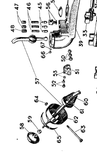
I have a new question relating to the gearshift. I’m missing part 65, called a 38560 C.865 Lock Plate. What is that thing? What does it do?
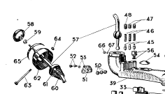
![]()
Do you have the lock tab for the setscrews that hold the dome in position Rob?
that`s what it looks like to me. Correction set screw and pivot bolt.
Peter B.