I’m reassembling my '66 FHC IRS after many years of looking at the parts in several boxes. (I’m ashamed to admit how many years).
Lots of washers, bearings, seals, spacers, etc. that I have no idea order of reassembly or what goes where.
Any good videos or photos to which I can refer that might provide some guidance?
Any advice would be helpful at this point.
Signed,
Chris from Fenton
The factory manual has everything you could need. The blowups and numbers in the parts manual might help also. The trickiest part is just setting up the bearings for the hubs and hub carrier pinion shafts. Everything else is cake. The manual does a fine job explaining it although you’ll need to read those sections several times to fully comprehend it.
1 Like
Erica,
Thanks. I’m expecting my shop manual from Amazon today. Parts manual is a good call.
Thanks again!
Occasionally I hear reference to the “parts manual” can you specifically tell/show me what this one is? I want to make sure I’m not confusing what I have for a “Jag-bible-with-all-the-answers” book.
It’s proper name is the “Spare Parts Catalogue”. All the usuals sell reprints and they often appear on Ebay. That’s where I bought mine cheap.
Steve,
Jaguar published separate Spare Parts Catalogues for the different series cars. For your Series 2 car, you will want the the Series 2 catalog. Unfortunately, this is the lowest quality one. Unlike the versions for the 3.8 and 4.2 Series 1 cars, it doesn’t contain illustrations, and is also incomplete in some areas where it just references the earlier parts lists, as there were no changes. Richard Liggitt, a forum member, produced and published an illustrated Series 2 Parts Book, which can still be purchased through JCNA or at least one of the usuals. It is a great improvement over the Jaguar version, though not cheap.
I rebuilt my IRS two years ago and did everything but the diff since it was working fine. As mentioned by our experienced JL listers above, the Workshop Manual and Spare Parts Catalogue are the best start for resources. The project for me was not too hard and I was under pressure to have it all done in a month before leaving on a long Oil Leak. If all the parts are there then the cost for the more minor wear items is not excessive. There are two types of housings for the drive shaft bearings depending on your car number and there is a large wrench needed for removing the large nut that holds these together. I was luckily able to borrow one from a Jag friend. You will also need a DTI for some of the measurements in the workshop manual. Ask questions here if you can’t find them. The drive shaft bearing assembly must be at .003 to .001 and that is not in the manual.
1 Like
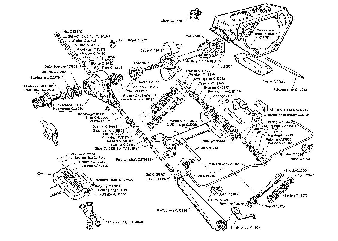
Rear Suspension with fastners.pdf (131.1 KB)
This is something that may help - i added the bolts and nuts to this parts diagram…
1 Like
Yes, John Carey’s videos are another excellent resource. I have used the videos on his Youtube channel extensively while working on my car.
1 Like
Also something to keep in mind if you are replacing the U/j’s, I believe that there are different tolerances produced for various installations. The ones you will require are ones that are produced to tight tolerances so that there is not to much play in the 6/12 o’clock position on the road wheel.
This is the diagram I use as well.
A few tricks.
Be aware that you will need a dummy shaft to assemble the hub carrier onto the outer end of the wishbone or you lose control of the shims. Make one out of 3/4" wooden dowel the same length as the outer width of the wishbone.
To assemble the 4 seal components on the outside of the inner end of the wishbone. I put them together and then wrap them in clingfilm to hold them together. Use a screwdriver to lever the suspension crossmember open to allow you to put them in place. You can then centre them and push the fulcrum shaft through the clingfilm.
You need to bolt the radius arm onto the wishbone BEFORE attaching the hub carrier as you cant get the bolt in otherwise.
2 Likes

This is an important point by Andrew. I used a mostly proper dummy shaft, but recklessly hammered it through not realizing the shims in the center were thin and mine caught on the wooden shaft and were rendered useless as I tore them all up. I had to measure them all and order new ones of the same size. I was more careful on the other side. ![]()
–Drew
1 Like

As Geo said, the shafts are 5/8", not 3/4". I took a lot of photos when I refurbished my Series 2, though some areas still have big gaps. If you go to my web site http://tinyurl.com/zgjkej3, you will find a section on the IRS. Unfortunately, it misses out a lot of the details, but may be some help. There is also a section titled Rear Hub Replacement that may contain some useful details. I also watched the YouTube video https://www.youtube.com/watch?v=qdNyUeFyh4E which has some useful info, particularly if you’ve previously rear the Service Manual to get the idea of what he is doing. Good luck!
Yes. That is the book authored by Richard Liggitt, that I referred to.
or use Barratt’s website – also detailed explored diagrams
Yes. Thanks Geo you are correct. I got confused converting from metric.
I used a 5/8 carriage bolt from home depot. Worked perfect.
1 Like
Chris,
JL lister Lynn Gardner posted a bunch of photos and steps in an IRS rebuild he did for a friend. You will find lots of helpful information here: http://xkebackontheroad.blogspot.com/2016/10/back-in-breach.html
He also built a special wooden buck for pressing out the hubs, but I didn’t see it when quickly looking through his blog. It may be in another project. The buck is important to properly press out the hubs without tempting fate by doing it improperly.
–Drew