I am once again struggling with a repair issue on my 1994 XJ6.
I replaced the head gasket this summer, as well as a door latch and door handle this past couple of weeks. After this I thought I was good to go with driving the car to a job site in Washington DC but then in the dense traffic of WashDC I discovered the hard way that the cooling fans were not functioning.
Now that I am back home I have been looking at the wiring diagram and the actual bits on the car.
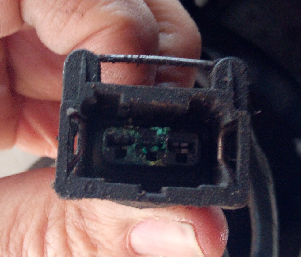
I pulled the connector off the fan switch on the bottom of the radiator and found a bunch of corrosion inside the terminals of the switch and the connector that snaps onto the switch.
However even though I know this is not good, I do not believe this is the real root cause of the problem.
When I looked at the MY93 - 94 wiring diagram, I think that there should be power flowing to this thermostatic switch from the fan control relay so when the car reaches a critical temperature that activates the switch the switch will trip and allow a circuit to ground through the black wire on the switch. When I checked these white wire connections on the connector for the thermostatic switch, there is no power in either terminal.
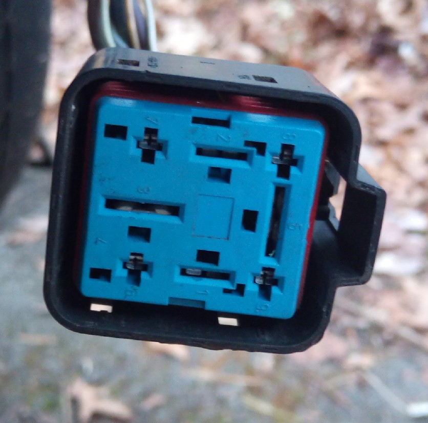
So I then looked at the fan control relay and pulled the wiring plug off of that relay. I have power to the relay through the big brown wire and from the big black with white wire (terminals 3 & 5).
I also checked fuse A2 and A7 in the left hand fuse box and these are good and have power to both legs of the fuse.
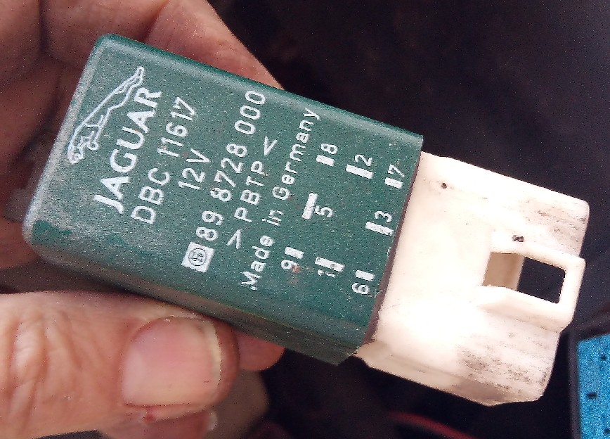
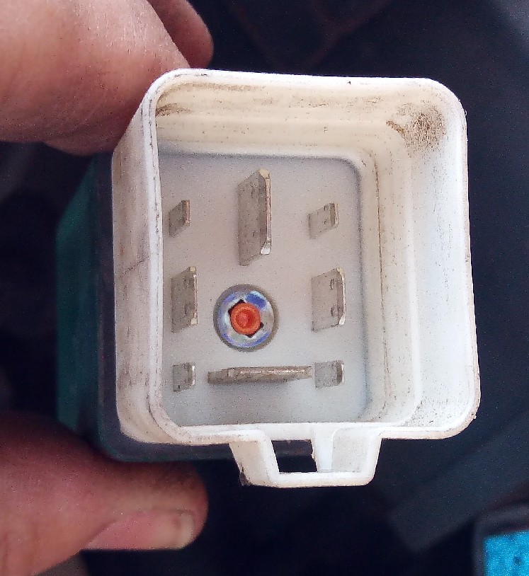
I believe my problem is with the fan control relay. I looked at the relay and it seems pretty well sealed up so I do not see a way to take the cover off the relay to get to the internal contacts.
If I have no power on the white wires going to the thermo fan switch in the radiator, do I have a bad fan control relay?
I would get a relay tester to see if the main circuit is working. If you don’t know what that is, it’s a relay device that you can plug into your relay slot that has a switch on the top of it. That way you can manually throw the toggle switch to turn the circuit on and off which will let you know if you have a bad relay. All relays can be opened up. Some not so easily but they were developed to be able to be taken apart if need be. You can go on Amazon and buy a relay tester kit that has the most common relays in use and keep them in your toolbox for any future testing that you might want to do. I great investment in my opinion.
Checking my wiring diagram for your model, I note that you didn’t mention if you have power from fuse A2 in the LH box on the Purple wire to pin #6 of the relay module base.
That is a direct “always hot” feed via the primary relay coil in the relay module through pin #9 of that relay base on the White wire to pin #2 of the connector for the radiator thermal switch.
Similarly, by internal wiring in the relay module, you should get power from the same source via the coil of the secondary relay in the relay module through pin #7 of that relay base on the White/blue wire to pin #3 of the connector for the radiator thermal switch.
If power is present at all of the points mentioned above and you ground either the White or the White/blue wires at the removed connector of the radiator thermal switch with the fan control relay module fitted then the cooling fans should operate.
If they don’t, I would replace the fan control relay module.
Thanks for the reply Bryan
I do not have any power signals to the purple wire on pin 6 of the fan control relay socket (checked with the relay removed from the socket).
Also there is no power signal present on either of the two white wires of the thermostatic switch so I do not think I am getting power to the pin 7 of the relay socket.
Is it possible that I am not getting power feed from the back of the driver’s side fuse box. I do have power signal across both legs of the fuse but Lawrence says it is possible for the circuit board in the fuse box to not actually transmit the power from the fuse out through to the actual wires leading out of the fuse box.
I might be wrong about not having power at pin 6 of the relay socket.
Late last night I went out and pulled the LS26 connector apart and I only have power on the LS26-1 terminal which is the solid purple wire. This is the same purple wire that connects to pin # 6 of the relay socket so I have to go back out and double check for a power signal on pin 6 of the relay socket when the relay is removed from the socket.
OK, I went out and confirmed my earlier findings. The purple wire on pin 1 of the LS26 junction definitely has power to it and pin 6 of the fan control relay socket has no power to it. I really don’t understand how this can be possible if the wiring diagram shown on figure 28 of the 93 - 94 electrical guide is correct. Those two points should be a common power flow but in this case, somehow they are not.
Here is a photo of the purple wires from terminal 6 from the fan control relay socket and pin 1 from the LS26 fan connector extending up into the harness.
The thinner purple wire on the right is the dead wire to terminal 6 of the relay socket and the thicker purple wire on the left is the one from terminal 1 of LS26
Both of these wires just extend up into the wiring harness that seems to eventually lead back to the left hand fuse box.
I was able to pull out the left hand fuse box and it seems to only have one solid purple wire leading to terminal 6 of the LS33 plug on the back of the fuse box.
Also if I pull fuse A2 from this left hand fuse box the power going to terminal 1 of the LS26 connector goes away.
So somewhere between where these two wires enter the harness at the front of the car and the back of the fuse box there is a splice where the two wires are joined.
And nowhere in the electrical guide does it give any hint where this LSS25 splice is located.
GAH!
No, after spending quite a bit of time that couple of days last weekend, I had to put the car back together so I could continue driving it. Fortunately I am not currently driving it in the awful Washington DC traffic I was in that previous week and it has been very cold here where I live. I hope to get back to the diagnosis efforts tomorrow or the next day.
My tentative plan is to pull the plastic liner out of the driver’s wheelwell so I can take a look at the wiring harness that runs behind it to see if I can find any damage to the harness or maybe an obvious indication of where that LSS25 splice is located in the harness.