Engine Development - Inlet Ports

I am attempting to rebuild a Jag V12 with a view to achieving in excess of 700bhp in normally aspirated guise. To this end I have been analysing what others have done and have been interesting primarily in asking “what would they do now?” if they could.

The output of the engine is constrained by stress limits in the block and flow/stress limits in the heads. And combustion efficiency. I propose (sometime in the distant future) to publish a web site with details of my investigations into these areas.

I thought I’d open a can of worms by publishing some info on the head flow.

First a note on simulation. In my day job I design stuff. And over the last few years, simulation has become a vital tool in understanding and optimising designs. Fundamental to my design process is to start by simulating a known entity. If the model matches the measured outcome, then you can have increased confidence in the model. Also, there is no substitute for detail. The more care and attention you make to the detail of the model, the closer the simulation result.

More Power!
There have been a number of posts over the years in people asking “what can I do to get more power” and invariably the answer has been “don’t bother with big bore inlets” because the ports are the limiting factor, or something like that.

Let me share some results of a CFD analysis on the inlet ports.

Background
The heads I have analysed are the TWR Gp C ported (flat) heads. I have not yet analysed the standard heads.

My engine was supplied with 12 individual throttle bodies and 12 butterfly valves by someone experienced in “the art” of making power from Jag engines. However, it was almost certain that this was the first time they had built an engine with the potential of the Gp C heads.

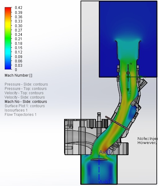
The computer model (using Computational Fluid Dynamics) tries to predict the mass of air that flows into the cylinder during an inlet event. The computer breaks up the flow area into thousands of tiny cells and then tries to solve the equations to relate each cell to its neighbour. The result shows velocity, pressure, turbulence and flow separation etc. The output in this case is air mass flow in grams per second into the cylinder cavity with the piston at BDC. I have converted this to cubic feet per minute, not through any love of the imperial system, but rather because the numbers become easier to understand.

The objective in this case is to maximise flow and maximise pressure wave effects (velocity -> momentum).

I have done a lot of work looking into using slide throttles, as there were what were used on the TWR engine. However, my conclusion is that correctly designed butterflies will result in better throttle response, better fuel mixing and almost no impact in maximum flow and be less problematic to maintain.

Baseline Flow
The Gp C head has an inlet port about 39.7mm dia (vs standard of 34.2mm - a 35% increase in area).
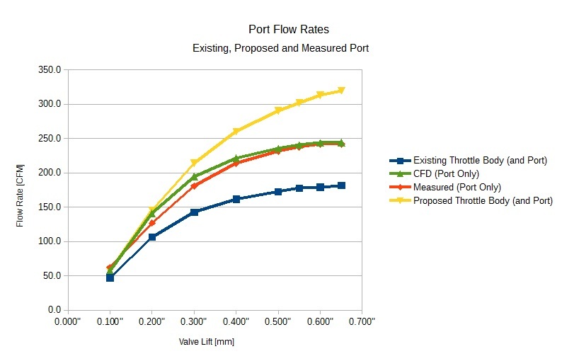
The graph shows 4 curves. The green and red curves are the heads flowed without any inlet trumpets or throttles. Red is measured by a tuner on his flow bench, Green is the result of a computer simulation. It is quite close, but I hope to put more effort into the valve seat detail to try to improve the simulation result at low lift. This port is flowing about 240CFM.

The Blue Curve
The is the flow through the identical port but with the throttle bodies and trumpets as supplied by the engine builder. The flow rate is now constrained to about 182CFM. Identical ports and valve. Restrictions are apparent in mismatched bore sizes between spacers, gaskets and throttle body (resulting in detached flow). The trumpet has a poorly formed inlet radius. The injector housing is copied from factory standard and protrudes alarmingly into the airflow. The butterfly is a traditional (8mm - 5/16") shaft with two screws. The screws were protruding considerably out the other side of the shaft, where they are split to prevent loosening but as a result are waving around in the airflow.

The Yellow Curve
Again, this is an identical port and valve. However, in this case, the trumpet has been designed based upon best principles. The butterfly is a shaft-less design I have developed with certain aerodynamic details. The injector intrusion has been optimised and the internal geometries have been tweaked to discourage flow separation and maintain velocity. Flow rate is 320CFM.

The other interesting observation is that in the case of the yellow curve, the flow rate is still increasing with additional valve lift. (Often people say there is no need to open the valve beyond a certain limit, because the curtain area is already greater than the port area).

Conclusion
I really just wanted to draw peoples attention to the fact that, despite the port being identical in all cases, the actual air flow into the cylinder is highly sensitive to detail changes in the upstream inlet arrangement.

I would venture to suggest that “the blue curve” is pretty representative of much of our enthusiastic efforts. The hardware looks great. A lot of wow factor. It would probably produce a great result on a stock head and be totally acceptable for up to 450-500bhp. (Which agrees with preliminary dyno results)

I expected a small improvement in optimising each component based upon the best published research I could find. I was completely unprepared for the size of the improvement. A 76% increase in flow is not to be sneezed at. And this suggests that the potential for this engine configuration is comfortably in excess of 700bhp. (Which agrees with published figures from TWR)

Cheers
Mark

3 Likes

great project!

it will be interesting to see your results ,in real life, a running and tested engine, dynod!

most of the engines with the guys on this site have engines closer to Grp-A and between 5.3/ 6.5 L.

most of the hi-HP jag V12 lose low end torque and only start big power above 5000 revs, few people drive around at 5000 revs.

BUT you results will be interesting, we will be watching, because this type R&D has not been investigated further!

thanks , Ron

Hi Ron, The proof will be in the final dyno run, if and when that ever happens!:thinking:

I should say that I am not trying to say this is the right way or wrong way, just wanting to share my thoughts.
In fact, to my mind, the more different ways people try to do things the better, in that we can all learn something from understanding other peoples thinking.

The following is an image of the inlet flow for the throttle bodes “as supplied”.

Areas of blue (or colder colours) are low velocity areas (or the inside of the plenum).

You can see the butterfly creating disturbance. The impact of the injector mounting point and the slowing down of flow on the back of the port and behind the valve seat.

Note that the only thing that is actually making this flow occur is the difference in pressure between the plenum and the cylinder. In this diagram it is essentially flowing “downhill” from the plenum at the top to the combustion chamber at the bottom. (Actual head is on a 30° angle). Exhaust scavenging can greatly increase the initial vacuum (at least double) to assist in accelerating the air at the start of valve opening.

For my mind anyway, it is a big assistance to understand the impacts of valve timing etc when you can actually “see” what is happening to the air.

The software is sophisticated enough to run a time dependent analysis (multiple cylinder and valve motion), but my mind is not yet sophisticated enough to make use of it! The static analysis above takes about 10 minutes to run on an 8 core CPU, with an area refined mesh (extra detail in critical areas) of several hundred thousands cells. I am not looking forward to trying to run a 10hr analysis, only to find I’ve forgotten some detail!

Regards
Mark

1 Like

Hi Mark
Very nice work…gotta love that CFD…!!! It’s just a bit expensive for the occasional use we would put it to…one day maybe…
It is no surprise to me that you are able to make rather significant changes by concentrating on the details of the upstream arrangement…each element of inlet geometry contributes to the pressure loss of the whole flow system.
It would be interesting to hear your thoughts on where the max gains could be obtained on the “standard” inlet arrangement so that those of us with the desire could improve things in this department .
Again…nice work!!
Regards
Matt

1 Like

you show the flow past the inlet valve, but from the end view,(front to rear), if you would do a sim. of the side view,

it would show a large area of flow disruption when flow hits the side of cylinder wall , that is normal in two valve engines , where the inlet is close to wall!

just quick observation.

some pix of stuff when Jag was R&Din the V12 ,1967, notice the fuel injector placement up in the trumpet so as to not have a protrusion into flow path, and more time for fuel vaporization of the atomized droplets, nice long runner length!

also the heads for TWR GrpC were very expensive and hard to find!

there is a guy in Australia doing some new pre-HE(flat head), copying the GRP44 , TWR heads, time will tell tho!

pix 44 1985 Daytona FL. Rolex/24 hr race ,car in pits slide throttles.

im trying to get another engine pic, but i cant get rid of the PDF block.

, darn computers, course me being and old guy, i still think com. are alien

quick change of subject, sorry,.

have you thought about forced induction(turbos), makes all the problems of getting air into the cylinder reduntend.

theory says if you can make 14.7 psig in the inlet manifold ,HP will go up 100%, it does not quite get there but a good pressurized inlet manifold system can make 90% HP increase.

sure saves a lot of R&D stuff.

anyway onward

and something to think about is ,what is the biggest restriction of getting air into the cylinder??

the valve presents itself , just like a big door!

stupid valves are always in the way of air flow, more so than any other thing in the complete inlet flow path from beginnig to end.

mark looking close , it seems the flow gets rolling trying to get past the FAMOUS short turn radius at the valve seat(red area).

Hi Ron,

One of my brothers thinks I am mad. But my other brother (who is a doctor but builds old historic wooden boats by hand in his spare time) understands. For me, the project is the journey, not so much the ending.

For whatever reason I have become fixated on getting this engine back to running in its original glory. It was a qualifying motor at Le Mans in 1988. BUT, I want to try to make it better. So turbos are not really in the equation.

I was hell bent on putting slide throttles on it (the original slide throttles being sold to two customers … mysteriously they didn’t appear with my heads and turned up on someone else’s … fairly typical of this industry! ). But I am reasonably convinced that they are more trouble than they are worth.

If I ever get this running, wide open throttle is not a place where I will be for very long at all. I am much more interested in part throttle response as I won’t have the downforce to produce the grip they had.

I suspect the major limitation will be combustion chamber. And I think there will be gains to be had in detail work in the piston crown. There have been some interesting studies in directing flow with grooves etc to improve squish and fuel burn and speed up burn rates (minimise detonation), allowing higher compression. It’s just too big an area with mixture “hanging around” just waiting to be ignited by the wrong thing. Thermal coatings might help.

1 Like

stupid valves are always in the way of air flow, more so than any
other thing in the complete inlet flow path from beginnig to end.

Which is why, during WWII, Napier and a couple other aircraft engine
companies came up with sliding cylinders that opened and closed ports.
They were clearly onto something because the engines in question had gobs
more power than their poppet-valved brethren. Of course, they also
considered themselves lucky to get 100 hours between overhauls.

I have long wondered why engine designers insist that the poppet valves
have to fit within the cylinder. As long as the head of the valve doesn’t
extend farther down the cylinder than the highest point where the top ring on
the piston reaches, you can scallop the $%^& out of the side of the cylinder
and fit valves that are waaaaaay larger than would fit within the cylinder. The
combustion chamber shape may get a bit screwy, but you could get gobs of
flow in and out.

– Kirbert

1 Like

Matt, I am pretty sure that flow increased by 3% (don’t have the numbers to hand) when I added a radius to the trailing edge of the butterfly. I will try to model the standard manifold, because once I have the model, it only takes a moment to run a simulation.

Mark

Mark, whilst I do agree TRW achieved more than 700BHP from the V12, they did it with a 7 Litre engine.
The best they got from the 5.3 was 510-520BHP (see TWR AND THE JAGUAR XJS by Allan Scott).
Even the 6.2 Litre 4V head engine they developed only got 670 BHP.
I myself have produced many 6 Litre race engines with standard stroke and 95mm bore to allow larger intake valves and the maximum BHP produced was only in the 610-615 range.
Your comparative flow curves of Blue and Red seem to indicate that the throttle body is a major restriction, not so, it is the design of the plenum that is the problem. The throttle body has a rating of 500 CFM. I have produced engines of 500 to 600 BHP for street use with a single throttle body on custom plenums.
As an aside, I have also produced 4V race engines using the AJ6 heads that produced from 760 to 850BHP., depending on capacity.

2 Likes

pic of 1967 Jaguar R&D V12 twin cam, it actually made 500HP BUT at 8000 rpm.

check out the straight runner tubes, fuel injector way up above the th.plate, gives more time for atomized fuel droplets to vaporize, and the fuel/air charge to build up some inertia weight,(ram effect).

for a good street car you need torque in the 2500/4000rpm Jag v12 over square bore stroke, needs all the stroke you can afford $.

you are correct about the slide throttle plates ,some guys had sticking pedal ,and you know that aint good when you coming into a corner at 175/200 mph, Daytona 24 races!

seen a set at a swap meet (daytona ) and you could not move them stuck 1/2 open for yrs ,in back of barn!

carry on, the knowledge you learn is worth more than anything else!

and they idle way high.

notice the 12 TBs slant to match the port angle, NICE, if your gonna do it ,do it right!

Hi Norman,

Yes, the configuration I’ve ended up with is about 6.7L in a 96 x 78 format.

The bore is not quite as big as some. And the stroke is not quite as long as some.

I will try to do an analysis of the existing ports and inlet manifold at some point.

Mark

1 Like

Hi Ron,

Following is the image you were looking for, showing the shadowing of the valve against the liner wall …

This adds velocity flow vectors …

This is a 48mm valve in a 96mm bore. I need to tweak the model to produce a standard bore and valve and see what happens.

Rgds
Mark

1 Like

as usual i always ahead of the curve! 1994 coatings. Swain tech NY.

my V12 has thermal ceramic coatings , piston tops, Exhaust ports, and complete cyl.head deck surface, along with valves top and bottom of valve heads!

i seen many jag V12 go down because of overheating issues, its sad after 21/23hrs racing and you lose a head gasket, and GRp44 and TWR tried everything , like Cooper rings , Nitrogen filled SS hollow rings, grooving slots,etc.