Actually, you might notice the yellow line tops out at 320 on the graph. However I have extracted an additional 9.7 CFM by optimising the port seat radii but haven’t included that data on the graph.
1 Like
hi mark, it would seem that with such a huge port, that at low rpm port velocity would be quite low(not much air), and torque would suffer signifiantly!
a usable engine for a street car needs torque more so than HP, hp being just a math formula, torque being what we actually feel and use!
a thought , just say you have a 3500lb car without an engine , you have available two engines?
one has 300hp, hp at 5500rpm, torque 700 lb.ft. at 2500rpm.
the other engine is a F1 takeout, rated 850hp, at 16000rpm, torque only 200 lb.ft at 12000rpm.
question what would give the best results, #1 engine or #2 engine?
give it some thought,
question , is there any way to get the air flow up to say 300cfm at .400 lift?
ron
i believe that Dr Quail, knows a guy Norm Lutz that built some custom inlet manifolds , with much larger Plenums, like 5-6" inch rectangular shape, and on a 7L Jag V12 made around 650-700hp.
1 Like
Hi Ron,
I haven’t analysed the initial results in any detail, but late last night when I got the first CFD results it appeared that the flow velocities through the standard port were very low. (Much lower than the Gp C port).
Low velocities imply low momentum (mass of column of air x velocity). So my first thought was “Oh. That’s odd. It won’t respond very well to inertia tuning effects on the inlet”. I expected to see the port max’d out in terms of velocity.
I should say that a number of things struck me (for what it is worth):
-
The flow number agreed with expected power outputs of the engine. Phew. So presumably the model is working and is in the ball park.
-
The factory valve shape is very good. That is, the radius and shape of the back of the valve was a lot better than my larger “Gp C” valves. (In fact I am going to order new valves based upon some of this research) This nice taper helps guide and promote the flow. Flow rates at low lift were slightly better than with the larger valves and ports.
The valve I modeled is part number C29347. This has been superseded twice I think with later part numbers. It is possible their shapes have changed slightly. Or perhaps it was a material alloy upgrade?
-
The shape of the valve seat was also very good. That is, the “taper” blending the seat into the port was much better than I expected. It appeared to me to be a nice radius, not multiple angled cuts and rather nicely done. Again, as a result flow was showing very nicely managed around the valve opening area.
-
The computer calculated weight of the valve is heavier than the real thing. This is odd and I need to investigate further. The real valve weighs 86gm, while the modeled valve weighs about 92gm. I usually use the part weight as a cross check that I have the model dimensional accurate. In this case I double and triple checked. I can only assume that either the stem is hollow (not sure why on an inlet valve), or the valve material is an alloy of steel with a lower density than stainless. (The model assumes stainless steel, perhaps the real thing is a more exotic alloy?)
-
The port entry to the head is strange. The port is 35mm (from memory) but immediately blends to about 30mm very soon after port entry (~5mm). This may be an attempt to increase the velocity before the injector, or maybe simply required to provide clearance for one of the outer head bolts. Either way, this transition doesn’t occur in the Gp C ports and may be a significant deterrent to flow.
My first thoughts there are that there is probably not much point “porting” the inlet manifold, as it is already significantly larger than the average port diameter. In fact, it may be beneficial to reduce the manifold diameter or introduce a taper into it (either of which would be difficult).
The impact of the throttle bore is a different matter, as it is feeding 6 cylinders and providing a virtual link between the small plenum and the small air filter “plenum”. A larger bore may well enable a larger virtual plenum with some benefit.
With a bit more work I can compare flow rates for the different cylinders. I am interested to see how the different manifold runs effect the cylinder flows. At first glance, they look sufficiently different to make a measurable difference. Which would in turn lead to different mixtures from central to outer cylinders. Is there anecdotal evidence that outer cylinder run lean? I expect to find higher flow rates on the central cylinders, meaning outer cylinders would run rich??
As an aside in order to make ~300 bhp the engine only needs to flow on average about 500cfm. Which requires the port to flow (on average) only 42 cfm. Not much. However, the valve is only open (say) 260° out of 720° and of that it is really only achieving peak flow for a very short time. The only thing driving this flow is the pressure differential between combustion chamber and atmosphere. If you have decent exhaust tuning present, then the vacuum in the cylinder can be very large at the opening event but will be quite weak at peak lift. David Vizard points out that people are experimenting with low angle valve seats (~30°) that can double the flow rates at low lift, effectively increasing the apparent valve size. There is no point flowing more, if you can’t burn it. But then, you can’t burn it, if you can’t flow it in the first place.
Cheers
Mark
1 Like
Hi Mark
Very interesting info.
As a matter of interest…the inlet gas velocity “through the throat” (according to Walter Hassan in his 1972 paper to the SAE…) is 321 feet/sec at 6250 rpm. Does this compare well with your analysis?? Close to 100m/sec is a fairly fast airflow…but I am assuming this is max peak flow…
Valve lift is 9.525mm and “Valve Crash Speed” is 7840 rpm. Comfortably under the theoretical max rpm of 8330 limited by piston speed. Sounds like an impressive V12 engine!!!
Possibly why we persist with these beasties…
Regards
Matt
1 Like
The inlet valve material is EN 52 . The exhaust is Austenitic steel 21-4 NS. If you check the properties of this material you’ll get a cross check on your model to confirm the weight.
Regards
Matt
Thanks Matt,
Using a mass density of 7700 kg/m^3 (21-4NS steel) I get 89gm for the model, which is a bit better. Can’t find the density of EN52.
The following is a static flow comparison between cylinders 1-3. (I assume 4-6 are a mirror image).
What is interesting is that the central cylinder pair appear to get 2% more flow than the outer pair.
Assuming #1 is standard, then #2 is down -0.3% and #3 is up 1.9%. Anyone care to speculate what this might do to mixture in the central pair of cylinders?
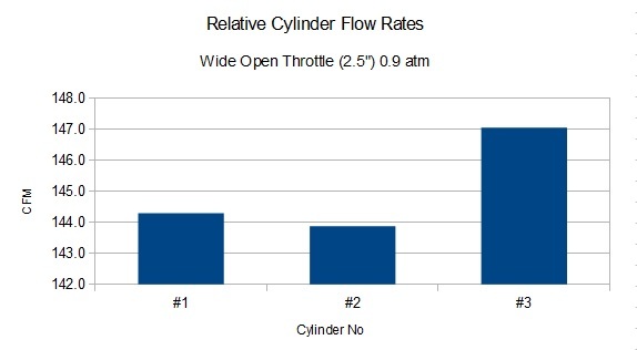
The flow is slightly higher than I reported earlier because I didn’t have the butterfly fully open. I assumed than a “mostly” open butterfly would not effect flow to one port because it is so large. I was wrong.
1 Like
hi mark, interesting you mention low valve seat angles 30* vs 45*, way back around 1960, i built an engine a V8 ford, and was studying valve seat angles , so went big time change and took the inlet seat to 15* from a 45* seat!
engine made about 5% more low end torque and noticed no upper change in power!
well the car won many races ,finally administration said cheating and shut him down until engine was disassembled and check out , YEAH i had some other small tricks , but i learned a lot!
now some place i have read that some guys are using 50* exhaust seat angles, seems it works fairly well but possible sticking in seat bore when super hot and metal changes struchture! donno .
if of any use a factory cam has 254* seat to seat timing, pre HE, , while HE has 248* seat to seat! theory says that HE is good for mid range torque increase!
but that falls into a yes, becuase HE head doesnt flow well at hi rpm anyway!
almost any inlet system never flows equal to all cylinders, to may variables.
OK just say if one could get all the cylinders to flow absolutely even , how much hp would be expected , YIKES NOT 500hp more, thats not realistic, (( i think).
what did you think of my thoughts on the 2 engine above, 300hp vs 850hp, its silly. but interesting for conversation.
ron
Hi Ron,
What do I think about your 300hp vs 850hp example?
I think you have a twinkle in your eye and are spoiling for an argument!
What would give the best result? Well … the best result for what?
My wife drives a lovely supercharged 3.0L V6 from Audi. It is truly stunning to put your foot down in that car; it goes like stink from idle - but has a curious lack of top end grunt that leaves you disappointed.
My other toy is a tweaked Audi RS2, which is the opposite. A gutless wonder at low rpm but kicks you in the kidneys when you hit > 3,500 rpm.
Both are fun to drive in different ways. However, on the track, or on windy roads, the RS2 is always “in the zone” and is a real blast.
In a drag from the lights, the supercharged 3.0 will leave the 2.3L turbo for dead. (Unless you drop the clutch in 2nd while red-lining the RS2, which would be a very unsympathetic thing to do - and what the journalists must have done).
But on a track or a windy road, the RS2 will dance on full boost from corner to corner and leave you with a smile a mile wide.
Sooo … if I were driving around town, I have the supercharger. If I were on the open road, I’d have the turbo.
The car this engine is going in is about 1050kg. Say 2314 lbs. Traction will be a problem as it is only 2 wheel drive. There is very little aero. Secretly (I don’t say this out loud) I hope it’ll be a little down on torque at low rpm, so that it is drivable. So I can tootle around sub 3,500 rpm. And in those rare moments I can open it up, then I hope it’ll have traction and go like stink.
The answer as to which one is better, is the one that can deliver the most usable power within the rev range that you can maintain. And that might be the 300hp engine around town. Or it might be the 850hp engine on track …
Cheers
Mark
1 Like
LOL,LOL i wonder what gear ratio would work with no torque and lots of hi rpm revs ,16000rpm.
be a funny lookin transmission, and final drive, most F1 engines stall dead at 7000/8000rpm better have a good clutch!
with one of my jag V12,manual shift, i tried a trick i;d heard of ,side of road with car at rest, engine off , put gear lever in 4th gear, clutch out , turn key to start, car pulls away no jerking or stalling, all the way to 100mph or more.
cant do that with 4000lbs of car and a 4cylinder engine!
HEY wait here, the car your gonna build is going to be ONLY 1050kg(around 2314lbs), what is it any pix close to it?
the Jag V12 engine and trans, will be close to 1/2 that weight??
your CFM flow chart says only 3CFM between 1-2 and 3, thats not much difference, what could that be in usable power couple tenths HP!
, AFR close to not being relevent or correctable, going from one side of track to the hill on other side track!
like temp, humidity, air density,etc.
quick change of subject:
i know you have heard about the great USA engines at low costs, like GM LS3 crate, or Ford Coyote crate, or takeouts!
shocking fact is last week GM Cadillac won the Daytona 24 race using a modified GM engine, the only car in contention using NA , most others were turbocharged!
for a very special Ford would sound great the new VOODOO Ford , OOHH LALAH, screamer 9000revs, with warrentee!
shocking fact is last week GM Cadillac won the Daytona 24 race using a
modified GM engine, the only car in contention using NA , most others
were turbocharged!
Yeah, but that’s not a real world comparison. Those cars are limited using
inlet orifices (I think!), meaning a turbo provides zero power benefit. The
choice to use a turbo is in order to use a smaller engine and hopefully save
some weight – but these cars have minimum weight limits too, so really
there’s no reason to go turbo at all.
I think it’d be fun to be an engineer for one of those teams. The regulations
put the priorities so far from what most motorheads are familiar with that
none of the standard rules of thumb and tricks of the trade apply. In fact,
what these teams SHOULD be working hard on is efficiency – reducing drag
and losses.
– Kirbert
1 Like
mark , couple pix of old jaguar engineering of V12, some relevent some not so much.
done before computers were available with software needed! (i think).


hi mark,
i see you are an AUDI guy ? maybe .
one of my to do lists, is locate an AUDI V12 Diesel engine with ECU, from a 2007-2011 Q7 SUV.
if you are around Europe and might know of one , let me know??
i have a completely different plan for an XJS coupe.!
reason for my interest, is back 2007 at the Road America race track , race had the sports car races,Le Mans types, you know factory Penske Porsches ,unlimited money,and other good cars , also Audi was there with there R-10 DIESEL cars.
well Audi won race, but the porsches were fantastic in braking and cornering(as usual), but on the long main straights, the Porsches screaming 10000+ rpm , the Audi would just chug along past barely reaching 4500/5000rpm , right on by the Porsches!
Penske was pissed, shortly after Audi diesels were restricted with some weight increases, and air restricters, fuel tank limits! wonder who pushed those rules?
when you see the car run with your own eyes, and talk in the pits/paddocks, you know there is serious potential!
…but on the long main straights, the Porsches
screaming 10000+ rpm , the Audi would just chug along past barely
reaching 4500/5000rpm , right on by the Porsches!
It might help to remember that the Audis and the Porsches were in different
classes. The diesel Audis were in the LMP 900 class, big engines and heavy
cars. The Porsches were in the LMP 650 class, much lighter cars with about
half the horsepower. A couple of teams had come close to winning races
overall from the 650 class, so just for grins Porsche set out to do exactly that.
I believe they eventually did score some overall victories.
Penske was pissed, shortly after Audi diesels were restricted with
some weight increases, and air restricters, fuel tank limits! wonder
who pushed those rules?
This was about when the ALMS went off the rails, applying various
restrictions to partcular models in an attempt to make the racing more “fair”.
Still, I’m pretty sure the biggest change that happened to the diesels was that
somebody figured out that a diesel engine should have a DIFFERENT size
intake orifice, because a diesel engine generates a different amount of
power from the same amount of intake air as a gasoline engine. Penske had
nothing to do with that; he wasn’t racing in the same class, didn’t care.
when you see the car run with your own eyes, and talk in the
pits/paddocks, you know there is serious potential!
Only in a racing venue where a minimum vehicle weight is specified and
intake orifices limit power generation. Remove EITHER of those regulations
and diesels would be worthless for competition.
– Kirbert
I really believe that the best racing at Indy was when the only rules were basically displacement and blown or unblown.
Bob
889076
Plymouth, Mi.
1 Like
I really believe that the best racing at Indy was when the only rules
were basically displacement and blown or unblown.
That’s because we’re car nuts. When there are no rules, innovation runs
rampant, and we get to see all sorts of brilliant and nutty ideas being tested.
Those days of racing are apparently gone. Today it’s all about driver skill, all
the cars are as close to identical as they can regulate them.
– Kirbert
agree , SPEC cars.
the little 4 cylinder diesel that ran up till last year did quite well , actually run a 4th overall for a while, considering against the v8 cars, just ran out of money, for a bigger engine, then would be in a different class again!
i was at the Daytona track 2009, 24hr race, just before Sebring, Audi pulled in with there big hauler, and inquired about making some test laps , not in a competion place!
administration said NO WAY , dont even unload it for just a show exibition.
could they have been worried? makes you wonder tho.