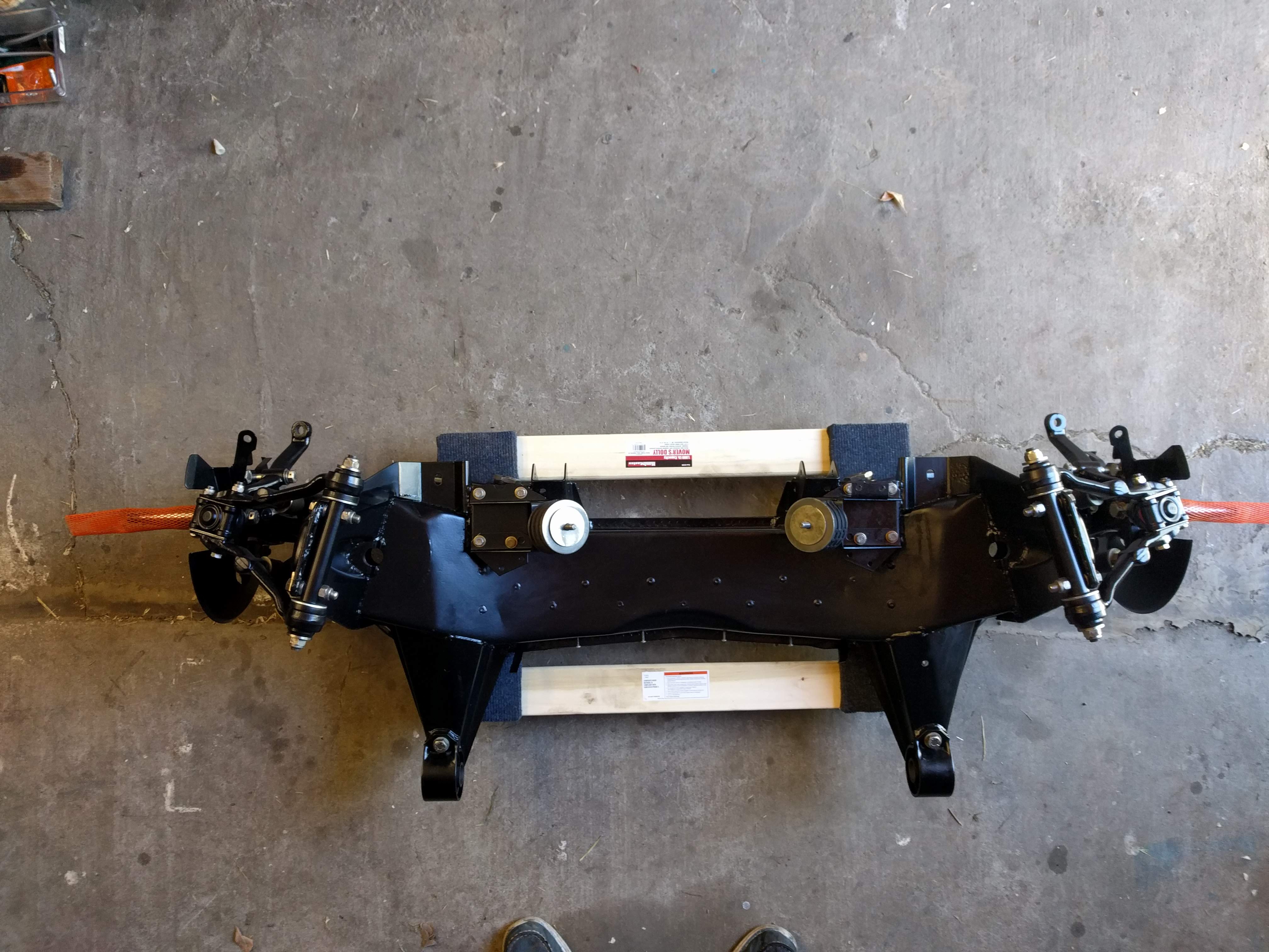
I am approaching the end of the reassembly of the front assembly.
I cannot begin to say how much of a delight it is to reassemble nicely powder coated parts with zinc plated fasteners, new bushes etc…
But, the order of parts was mostly lost in the powder coating process and I am uncertain that I have put the right bits on the right side.
Looking at the overall unit, now that it is all clean and shiny, I realise that the wishbones are not perpendicular to the axis of the car but swept backwards, a lot. And I wonder if the top arms are really symetrical and not handed.
Does look more angled than I remember on mine. Some years had asymmetric upper wishbones, some years symmetric. I think the S2 ones were asymmetric, though. But maybe I have it backwards. Yours certainly look symmetric. The lower arms were symmetric at first then became asymmetric (regarding location of the ball joint). Very curious! Looks beautiful.
On early Series III cars the upper arms were different with respect forward position and rear position…but not were not “handed”.
Circa 1983 the upper arms were changed. There were now four different arms: left/right and front/rear.
A quick perusal of a Series II parts catalog reveals the reverse situation. Early cars had four different arms: front/rear and left/right. Later cars had different arm front/rear but were not “handed”.
Are there any part numbers on the arms, by chance?
My clue was that the spindles fall into the same straight line and each is at right angles to the cross member. Odd assembly would seem to result in the spindles at odd with other stuff.
Sure is pretty. Almost a shame to expose it to road grime!!!
Decades ago, I was perplexed. My “Hot Rod of the 40’s” project. The straight axle would not fit into the wish bone. Each nice and clean and painted. Eureka. spin the axle 180 ! Now they mate. mating points at an angle. That established “caster”.
The beam axle had been dropped by a classic “blacksmith”. Mordrop. Located at the time in nearby Oakland, Ca. I ran across a cap with the logo in my stuff yesterday!!
I think in the end it all comes down to the lower wishbone and having the rest align to it.
On the lower wishbone the outer extension that holds the ball joint for the hub spindle is leaning towards either the rear (I believe the right set up) or the front (tf right and left have been inverted).
This is what I need to confirm.
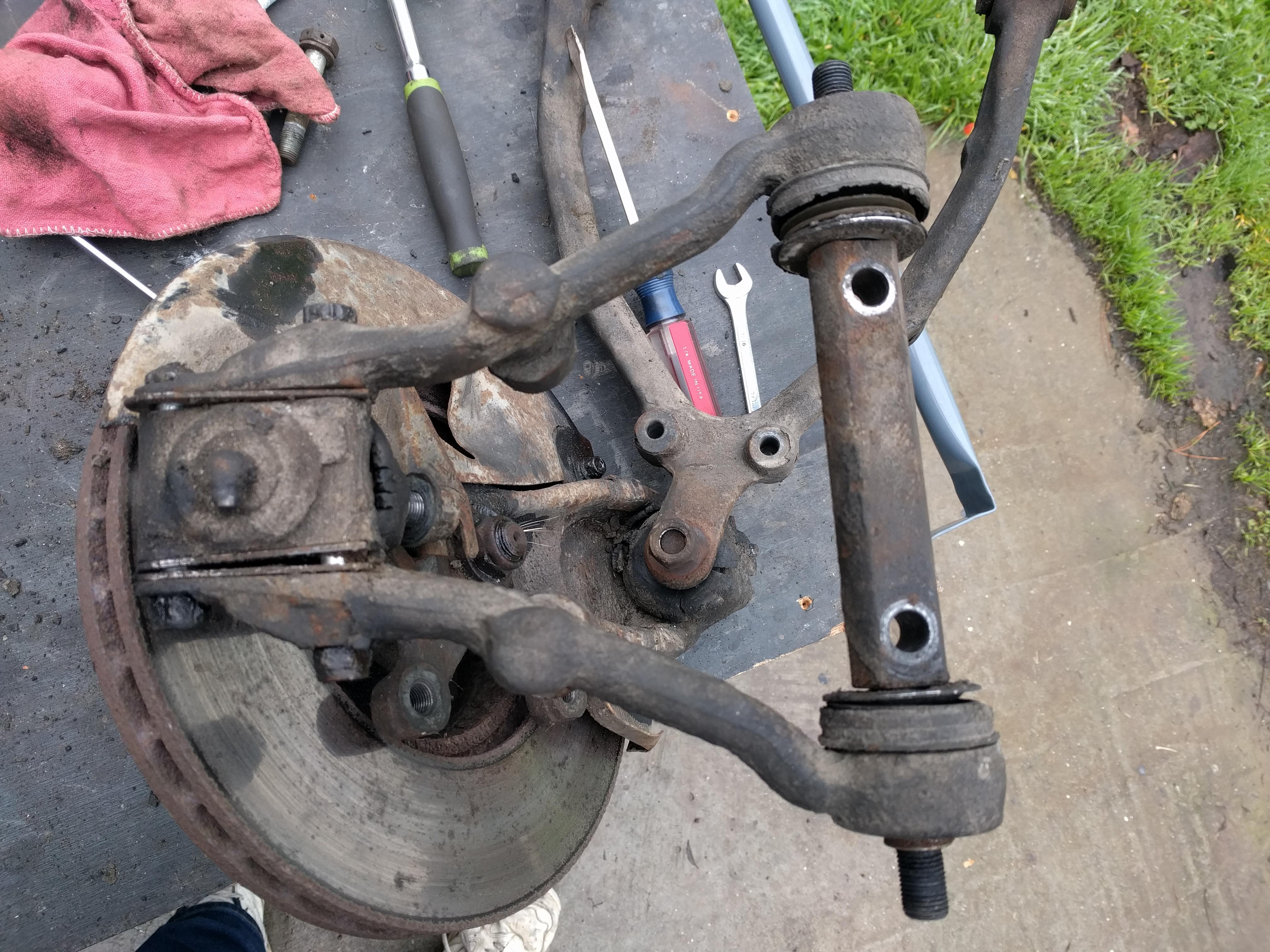
These photos below scraped off the Web seem to show the lower wishbone leaning towards the rear of the sub frame (or am I just trying to convince myself? )
Eric, I hope your assembly is “ready to go” but I just wanted to mention the content of several previous threads about modifications (DD is the expert on these matters).
I know little about Series 2, particularly the coupes, so this pertains mostly to Series 1. With the advent of newer tyres, there is some agreement that larger caster angles are desirable, as is slightly negative camber. On S1 cars, neither is achievable, especially if you’re trying to get both together. Some folks have put a very thick shim (like 1/4 inch) under the upper wishbone mounting, pulling it inward. And, some have fit the Series 3 lower wishbones, with offset ball joints to increase caster. You may already have the latter; I don’t know when they were introduced but I had thought it was during S3 production. And as mentioned, upper control arms were changed as well. I’ve never gotten it straight just which bits were in production during which years.
Hi Robert, thank you for this. I can see how easy it is to add some negative camber. In fact, I found out that on this assembly the camber shims on both sides are if different thickness.
And this explains why the two bolts on the inside of the upper arms assembly are so long… ah!
Honestly I have never put enough mileage on the car to see any sign on the tires
Well, it now looks like I goofed up.
I found a photo of the disassembly phase. The right side bottom wishbone here shows clearly (?) that the connection for the ball joint is pointing forward… !!!
Ah well.
**
Note also, on the lower picture, that there should be no gaps between the ball joints and the wishbone, Eric…
When the wishbone arms are tightened to the pivot shaft; they will have a ‘natural’ gap at the ball joint. This gap should be filled with shims - the arms should not be forced to close the gap by tightening the bolts…
The shims in this case are used for castor angle by moving shims to the front or rear as dictated by alignment checks…
Coming in late, but we did this exercise before and made a list of the several setups in series Jags. It is on the albums of the old site.
Good luck and - one wonderful piece of work
Hi Eric - Only just joined and have a similar problem however there are part numbers on the lower arms that can help out or in this case confirm XWB5105 (RH) & 6 (LH)