Giuliani, have repaired many of these shafts. You need to get an inner race for the Roller Bearing, Torrington B1612 and have the shaft machined for a press fit.
Giuliani, this seems to be a common problem with the all synchro box, and I normally replace the caged bearing with a full compliment one (Torrington B1612) as this has a higher static load rating, which, I believe, will “solve the problem”.
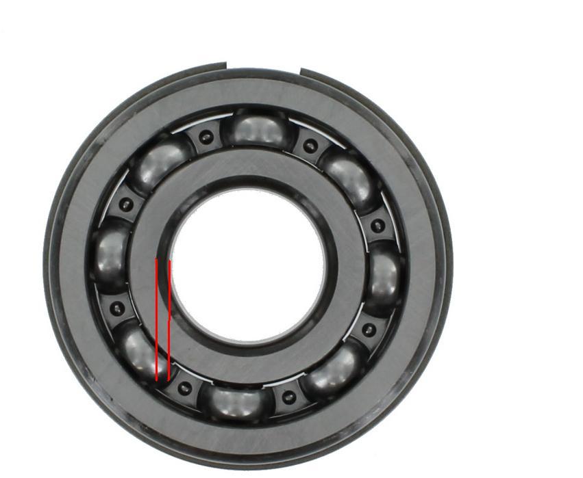
Well Norman, you would be wrong there. Yes, the Full Complement Bearing has a greater load bearing capacity, but its only marginally better and as the application in the Gearbox is not subject to great radial load, its irrelevant.
Caged, Drawn Cup Roller Bearings have a far higher speed rating than the Full Complement counterpart. Whats more important is that the rollers in the Caged Bearing, are held in better alignment and separated. The rollers of a Full Complement Bearing rub together and try and rotate each adjacent roller in a different direction leading to increased heat generation and wear. The Caged Drawn Cup Roller Bearing is the better choice in this application.
@Oliv69 The nominal size of the Main Shaft Bearing Journal is 1.000"
Well Norman, you would be wrong there. Yes, the Full Complement Bearing has a greater load bearing capacity, but its only marginally better and as the application in the Gearbox is not subject to great radial load, its irrelevant.
If the radial load is “not great”, then please explain why tis is such a common failure
The main reason for failure of this bearing is lack of lubrication. Its location shields it fairly well from splash lubrication and relies mainly on lubrication via oil supplied by the centre oil gallery of the Main-shaft. Without exception, where there has been complete failure of the bearing and not just expected wear, one or any combination of the following has been present:
Wrong Rear Main-shaft bearing used that has too small an interface margin between the face of the inner bearing race and the Oil Pump Drive Sleeve.
The Companion Flange Nut not tight enough. Typically, the Numb Nut that previously serviced the Gearbox had backed the castellated nut off to get the split pin to assemble when found that there was no alignment with split pin hole and any slot in nut when the nut was correctly tightened.
The centre oil gallery of the Main-shaft clogged with sludge.
Points one and two relate to the Oil Pump working inefficiently, or not at all.
There is radial load on the bearing, but nothing near the load carrying capacity of the caged variety of a Drawn Cup, Needle Roller Bearing and as I mentioned in my earlier Post, the difference in load bearing capacity between the two types is irrelevant where the load of the magnitude experienced in this application is concerned. The rollers of the Caged version are also better lubricated.
All that I mentioned in my previous Post is well documented in papers dealing with application design and the use of Guided Caged Roller and Full Complement Bearings. The following picture shows a common condition that occurs with Full Complement Needle Roller Bearing, that being misaligned, skewed rollers. This condition kills the bearing a shite load quicker than radial overloading, which I emphasize, does not come close with a Caged, Drawn Cup Needle Roller Bearing used in the Jaguar 4 speed Gearbox.
Hi Giuliani,
From your picture, it appears as though a sleeve has been fitted to where the original Bearing Journal was by turning it down and then affixing the sleeve by either press, or shrink fit, or by gluing the sleeve in place.
The prepared journal looks like quite a coarse feed rate was use. If the sleeve was pressed on you would see evidence of the crests of what is effectively a fine screw thread, smeared to some extent due to the ID of the sleeve being a smaller diameter than the OD of the turned journal. I don’t see that in an enlarged version of you picture, so there is a possibility of a Shrink, or Expansion fit, or the sleeve has been glued in position using a Bearing Retainer. However, the overall job looks fairly poor, so I doubt that whoever did the job would have taken the trouble to execute either a Shrink or Expansion fit of the sleeve.
Given that I can see no evidence of there being an interference fit with the first part of the Main-shaft journal, it could be that area has been machined down to be slight clearance fit with the ID of the sleeve so that the interference fit is only where the sleeve needs to be (makes the press fit just that little bit easier). Therefore, your biggest problem maybe in obtaining an off the shelf sleeve of the correct ID and OD for your purpose.
Correct fitting internal sleeves of various lengths can be purchased for Drawn Cup Needle Roller Bearings; for example, like the Bearings and Sleeves used in the inner bearing system of the rear suspension wishbones. The diameter the journal of your Main-shaft has been turned to will determine if you can use an off the shelf sleeve.
In the end of the Main-shaft journal you will find a threaded plug. If you remove this and you should in any case to ensure that the oil gallery is clear, you will be able to use the same Centre used when the journals of the Main-shaft were ground; use this to support the end where the new sleeve is to be fitted. The other end also has the centre used when the Main-shaft was originally ground. This can be used to carry out the machining between centres and should set the journals of the Main-shaft to run true, or you can grip that end of the Main-shaft in a 4 jaw chuck and dial the journal closest to the 4 jaw chuck to run true. When the Main-shaft is set either between Centres, or Centre at the end to be machined and the other journals running true using a 4 jaw chuck, check for any run out of the previous machining of the journal to be machined. This will determine what will be the max diameter you can machine the journal to and if an off the shelf sleeve will be available. This journal when finished must run true, otherwise all other journals carrying gears will run out, resulting in slightly different mesh characteristics of the Main-shaft gears and the Lay-shaft Cluster.
Brent, the failure of the main shaft hardening is identical to that experience by the counter shaft hardening due to high loading. You must remember that the counter shaft design is as per the original “Moss” box, from which time the bearing loads have more than doubled from those experienced with the 3.5L pushrod engines.
In more than 50 years of repairing Jaguar gearboxes, I have never ever experienced any one or more of the combinations you list as a cause of hardening failure of the main shaft
And what type of Needle Roller Bearing system do you think is used for the Counter Shaft? A Full Compliment of course; kind of defeats your argument with regards to the Full Complement Bearings being superior to Guided Caged Bearings.
The next gearbox we rebuild won’t be our first rodeo. We would rebuild more Jag gearboxes than probably any one else in Australia and we frequently see the three points listed in my previous email occurring in concert with failed Main-shaft forward bearing journal.
Many don’t comprehend how the oil pump in this gearbox is driven and the importance of not having slippage between the components. We have one car in work at the moment where the Speedo Drive is not rotating. I told the client that the cause will be one of two things; either the Companion Flange nut is not torqued up enough, or something is amiss with the Main-shaft Speedo Drive Gear. The best scenario will be the Companion Flange nut not being tight enough, as anything else will require engine and gearbox removal. Sure enough, the Companion Flange was not sufficiently tight and had all the earmarks of the castellated nut being backed off so as to fit the split pin. If the Speedo Drive is not rotating due to the Companion Flange Nut not being torqued up enough, neither is the Oil Pump.
The following picture shows the face of the correct, gearbox rear bearing that interfaces with the Oil Pump drive sleeve and even with an optimal contact margin, there is clear evidence of slippage between the two faces.
The following picture shows the bearing that most of the After Market usuals supply. It’s not hard to see that the majority of the contact margin of the correct bearing shown in the first picture, is taken out of play by the large radius between the face and bore of the inner race.
Norman, if it gives you a warm feeling to use a Full Complement Bearing over the Guided Cage variety, please continue, but it doesn’t alter the fact that the Guided Caged Bearing is the better choice for this application, with the following being just a few of the relevant advantages:.