This is a Ford BTR 4 speed transmission. This particular one is supposed to have come out of a AU Falcon.
I do have a question that I need to address as soon as I can, I need to replace the centre carrier bearing in my 1987 XJ40, and I was thinking about the idea of having a simple 1 piece driveshaft and I don’t know anyone that has done so up to today. Can anyone shed any light on this subject.
When I put a Supra 5 speed in my S2 V12, replacing a failed auto, I had a one piece tailshaft custom made by a specialist, no worries at all, I added a tailshaft hoop too
I think we are lucky to have this particular guy in town, he took the business over from his dad
I am sure that a single piece driveshaft could work on these, the shaft doesn’t really move that much because the diff is not moving, so really I think only the engine will move, but not much I would imagine.
My question is this: why did the factory choose a 2-piece propshaft, over the less-expensive single?
Hi everyone, today was possibly seen as a slow day, and while I may not appeared to be doing anything, I am quite pleased with what I have done for the day, I have tried a few different things to get this engine to go into a place it was never meant to be.

From this angle things appear to be in the right place, sort of? anyway it has a questionable amount of clearance for an oil pan. I need to get one soon.

From this angle I can see some things working out, and others will need some time to ponder over what I have. I really don’t want to move the engine any further forward if I can get away with it.

With the heads sitting in place, I can see if there will be enough room to fit the exhaust in this small place. I have some headers to try out but the 4 into 1 has a fairly large collector and it will not fit here.
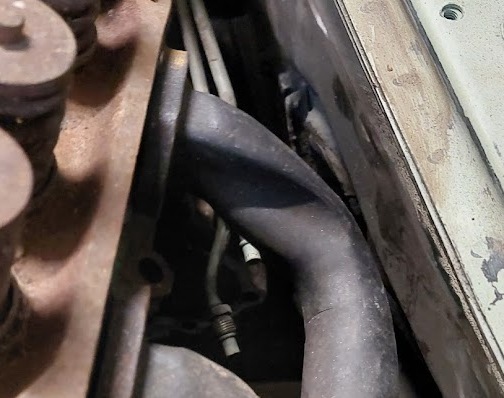
Here we have the header pipe in place, however it is on backwards. The idea here is to determine if I use a different type of header I may be able to get away with it, there is almost an inch of clearance from the chassis rail and the pipe here.

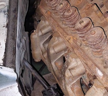
Here the other side of the engine shows I am confronted with a similar problem, and the same sort of room to play with. I don’t have the starter motor in yet so that will be another problem to deal with later on. Time to start looking at the different types of headers available.
1 Like
I assume you have the ability to weld: I would just get a pile of appropriately-sized J bends, a set of header plates, and piece one together.
I have played with a welder a couple of times, I am a boilermaker by trade, but this sheetmetal is a new ballgame for me, For me 10mm was as thin as I went up to 100mm with Biss alloy 400 for some of the jobs, I have seen some kits around to make up headers, I have thought about it, who knows it might still happen yet.
A MIG welder is an invaluable tool, and good 110/220 house current units can be had.
Possibly a matter 9f not having to do proper balancing. I think a one piece will be great, provided it is well balanced.
Out of curiosity what is the weight difference between the V8 and the I6?
The 302 Windsor engine weigh in at around 208.6kg where the AJ16 weighs in at 240kg. This means that I will need to change the front springs, either by compression weight, or at least ride height. while 32kg doesn’t seem like much, it is enough to make the car sit uneven front to rear, so a change in ride height will make the front suspension a little stiffer.
I am certainly not going to attempt making this one up, I am going to get it made up by a place that does make them, I have thought of just sending them the shaft I have taken from the car and getting the sizes changed and getting the Ford yolk put on the end, I am still undecided on that one just yet, I need to get this engine and trans mounted before I remotely think of the driveshaft.
I have a few different types of welder at my disposal, sometimes the MIG is not really the tool to use, (the big one is risky to my pocket) I also have a AC-HF TIG if I need to go a little more softly, and it also has pulse capabilities as well, I also have a designated gassless MIG welder that operates on a 10 amp line not just a 10 amp plug on a 15 amp machine, and my house has 3 extra circuits installed that are not RCD protected, after all a welder is theoretically a short circuit, At the time they were installed, I was instructed to have those power points labelled clearly stating they are not RCD protected to make it all nice and legal. My larger MIG requires a 32 amp power point to run, and I have been warned that if I have anything else in the house going when the big welders gets plugged in, it will blow the fuse on the pole. This will cost me $400.00 to get replaced if that happens. Fortunately I don’t use that machine unless it is really needed.
Sometimes things can look pretty awkward, and in this case I figured things wrong, I have often found headers can save you a bit of room to move where an exhaust manifold can eat away any space you may have uder the bonnet of our cars. I found that to be untrue in my case. I had some of the engines original manifolds for this engine, no idea what car they were made for, but they fitted in better than the headers could imagine to be.
This may look like I am not getting a decent amount of room here, but it certainly surprised me how much there actually is.
I have plenty of room here and it is not fouling any part of the car, and the added bonus of not having to touch the chassis rails on the car.

This picture once again makes things look a lot worse than they really are. I am extremely pleased about the outcome of todays efforts.
1 Like
I do realize that the bolts are not all done up, this will only give me more room when they are done, also remember that there are gaskets to go into some of these pictures, and that both the engine and transmission are dummies for the want of a better word, better to damage these rather than the item I will be using in the end, I am sure I would not be happy if something went wrong trying to make the engine fit, and it ended up damaging that beautiful engine or transmission, once all this is finished, it all comes out and the engine bay can be prepped for painting when I do the rest of the car.
1 Like
Well, that certainly looks like a perfect solution! On top of that, it will save you the time, effort and expense, of building headers plus it’ll make just about as much power. It’ll even be a little bit quieter!
The Gods are smiling for me it seems, I took the forward tailshaft and removed the Jaguar slip yoke, and sat in place a Falcon slip yoke in the transmission to see how much I would need to change on the shaft itself. The universal joint was left on the shaft and the yoke alone was on the transmission, it looked almost too good to be true, all I had to do was move the shaft forward about 20mm and it all sat in place beautfully.

Here at the centre bearing, the slip yoke here was completely pushed until it stopped, no force required. I had a feeling it was going to be close, but things were only going to get better.

Here we can see the centre bearing, it too will be replaced, no point in making sure the tailshaft is in complete working order, then skimp out on the centre bearing, the whole shaft will be biven a good going over.

As we move along the drive line, we ar near the output shaft extension. Here the Ford slip yoke is completely in the transmission and looking very much at home in there. There is only a small amount of movement with the shaft, 20mm all up.

There are no caps in place here the centre of the universal joint is just sitting inside the part that holds the bearing caps in place. However the shaft has not had the universal joint removed yet.

It really is a huge surprise to see how little I had to do to get this all to fit so nicely. The new universal joints are on order so it will be a fairly simple job of fitting the, and the centre bearing and Jurid joint, and the shaft will be done.
2 Likes
Some of you may consider these last few pics are only doubling back on myself, and it will happen from time to time. I am using this as a diary about the things I have done because I also have a tendency to forget what I have done, and I admit to forgetting what I have done and even doubled up on parts, so please be patient. These pictures are the completed tailshaft and all of it’s components, also the slip yoke I used in the end did not have the damper ring on it. and I am also getting a few measurements for the crossmember to support the end of the transmission.

I got a bit lazy and decided to rebuild the tailshaft in my lounge room, (too hot outside for my liking). So according to the jaguar dictionary this is a Jurid joint, however if you read the BMW dictionary it is called a guibbo loint from memory, these are the only 2 that I have read so far. then as we make our way towards the other end of the tailshaft we will find the centre support carrier bearing, followed very closely by another universal joint.

Here we see the centre support carrier bearing. I will be able to rest assured that the tailshaft is at least rebuilt from one end to the other, and I am very happy with the results. The next step was the slip yoke in the centre bearing joint, Hopefully it will all be finished before Mum gets home from work.

Finally the slip yoke for the front of the tailshaft, (goes into the rear of the transmission housing. Well that is what I am working with for now, I didn’t take a pic of the complete tailshaft, so you will have to be content with your imagination. Now for the bit that we have all seen before, and like I said this is primarily for my use.

In this pic I took a shot at the yoke from the rear of the joint, the clean looking part of the yoke os only about 2mm inside the transmission oil seal. I had to assemble the whole tailshaft to get it all in place nicely, the next part will be putting the centre bearing into its place, and try and get it all to line up properly.

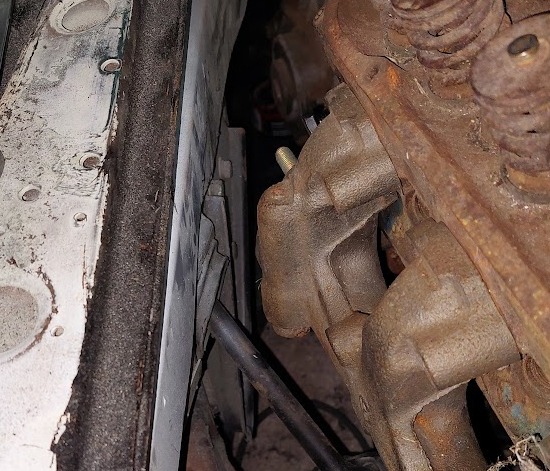
Here we have the drivers side (Australian model) where I will have to make up some transmission mounts. These are raised from the bodywork for some reason, I will be working on them next, the take them into the engineer to inspect them and make my file up for the mod plate. hopefully I can do the same as I did with the last car I put together. (Went through and passed on the first attempt).

these are pretty much identical just a mirror image of each other, and this side does not have any spacers welded into the mount base, it appears to only be about 10mm but it does make a very noticeable difference.

No sense in taking 2 pictures of the same thing in this case, you have probably seen so many of these it has become quite boring.

And finally the Jurid joint, that makes my tailshaft assembly now complete. Now it is time to take on the actual transmission mount, it looks fairly simple.
Jurid is just the name of the manufacturer.