Hi Rob,
Bill and I measured a few sets today and found them all to be very close to the measurements you made.
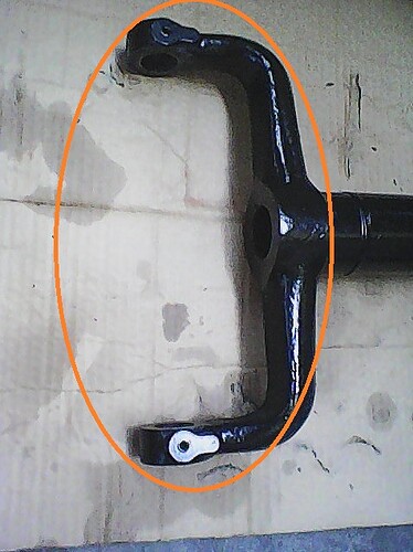
The reason the diagonally opposite flanges are the same dimension, within a small tolerance, is that the yoke itself (the part shown enclosed in the ellipse following) for the left and right hand wishbone are actually identical.
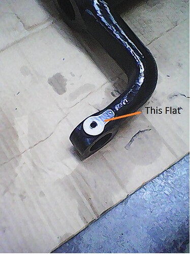
What makes the wishbone L and RH are the cross tubes mounting for the shock absorber and the yoke for the hub carrier. Accordingly, I believe that both the L and RH wishbones were machined with the inner fulcrum yoke fixtured in the same orientation, locating on the flats, one of which is shown in the following picture.
Therefore, both yokes would be machined the same, but the width of the diagonally opposite flanges appearing the same due to opposing handedness of the components at the other end of the wishbone.
The machining marks on the faces of the flanges and the way it washes out to the un-machined area on the inside of the yoke, strongly indicates the the surfaces were machined with the periphery of a Bull Nose End Mill. The typical way to machine features such as this, in a high volume production environment, is using Side and Face cutters arranged in a Gang set up; both faces of both flanges would be machined at the same time. However, the machining marks rules that method out.
There is no plausible reason for these flanges to be different thicknesses, particularly when there is only one length dimension bearing sleeve used in the assembly (only one part number for the sleeve).
Two solutions.
-
Only over length bearing tubes having the correct OD/ID dimensions are available. Accordingly, they have to be machined to length and therefore, they can be machined to suit the two different flange thicknesses.
-
Have the thickness of the thicker flange machined down to match that of the thinner flange (0.874")
The wishbones would be relatively easy to set up by locating them on the flats shown in the picture above and the inside face of the thicker flange machined to bring the flange thickness to 0.874".
Any machine shop with a horizontal mill would be able to machine the part with the Tool Holder located in the horizontal spindle of the machine.
Brent


