Does anyone have a clear picture of the volt guage and instrument voltage stabiliser on the back of a series two jaguar xj6. I pulled my volt guage out, removed the wires to the stabiliser and now I don’t know which ones go where. If you have a picture for I’d can you send it to. jburrows068@gmail.com as I don’t know my way round the forum. I don’t own a computer or cell phone and the computer language is a mystery to me. At 75 years old I don’t want to learn all the technical terms.
John, this will take you to a photo Jochen made of his Series 2:
http://www.jag-lovers.org/include/iv3.php3?zx=SdAEzw4IiM8ED8ZK%2FZnkxwXHDwWencoEzgcYtq2j3L1HN6OavET8PwvO2gpCvAwPi5jc98kfRd3dxDz4QPvS1Qw3CUz81dj998kfQdTHBkW8CxTZ1PdC9kk21doFMQo%2BMdrPBUD2QjzKyw4FxUk21pm7Bd1TRouZ2iX7Ghjf3uZJyRI8urbXK88nQdy7DhYCHSGqtuAC6CoBqbgCFsgm85ibyBjbKR%2FAruc2CSEQq%2BDcIusoG9%2B33BjZGyes3sv3yQ4ArLLXSAIqENbP7RT%2BSxyrt%2Fs4yyYGst%2FXRdlHPsm12R8GI%2FOYm8gYBzon36rlB90a85ibyRa8CwOZqrw1Akw7o533C8wJMJ2eyAIHEQSen89M0BL%2FmJnOAw8PAZaWxgTJOvCh
Just click on it and you will see the picture.
Good luck
David
Thanks for the advice, I have looked at those pictures and they are very clear on one side of the dash, but the one showing the instrument voltage regulator is partially obscured. I found another one where all the instruments on the back were clearly visible, except the voltage one. Then I watched a man showing how to take out the dash, it took a while and he finally started taking out the instruments, but when he got to the voltage one he just said, it will come out just like the others. Then I found out that I had to take out the speedo to get to the voltage guage. It’s so easy in the U tube video. You just place your hand on the speedo glass and twist anti-clockwise and it pops out. Why is it always so easy to do these things in a video when in real life it doesent work that way. I watched a video of someone working on a mini engine, the ratchet and two bolts fell down the back of the engine and vanished. I thought, ok that’s how it goes with me, let’s see how he finds them and gets them out. He never paused cos right away I saw him using that ratchet to install the two bolts. Aren’t videos very instructional when that happens.!!! I have found that every garage I ever worked in on a car has an invisible black hole somewhere in the floor. When you drop a nut or bolt that you don’t have replacement for it goes straight into that black hole.
1 Like
Remember that cars are sometimes done in either RHD and LHD versions, John - so check which is presented in a video. There are subtle, and sometimes more than subtle, differences. Like the spedo/tacho twist off in opposite directions…
Frank
xj6 85 Sov Europe (UK/NZ)
**
Yes, even when you know which way the instruments twist off depending on which side the steering is, they can be very hard to remove. A strip of tape over the glass can help to grab it. Prising off the center cluster helps as well.
I tend to think that it is unlikely that the connectors on the jags are messed up. Normally, there’s a male and female and if more they are often marked. From the picture I sent I think you can guess safely enough. The photo is from a RHD, maybe it matters.
We all share your frustration. Things often seem easier if you don’t have to do it yourself! And the number one rule, if it falls to the floor it is gone. If it falls somewhere else it’s gone forever. At least we have YouTube.
John!
I have a 78 XJ6 ser.2 , copied part of the schematic for the stabilizer
for you
Let me know if you get it? Walter
I will need your e mail
Walter
John,
no problem. Pic #2 of the album David kindly linked in shows the general orientation of the voltage regulator on a RHD car. Here’s the picture linked with a better resolution.
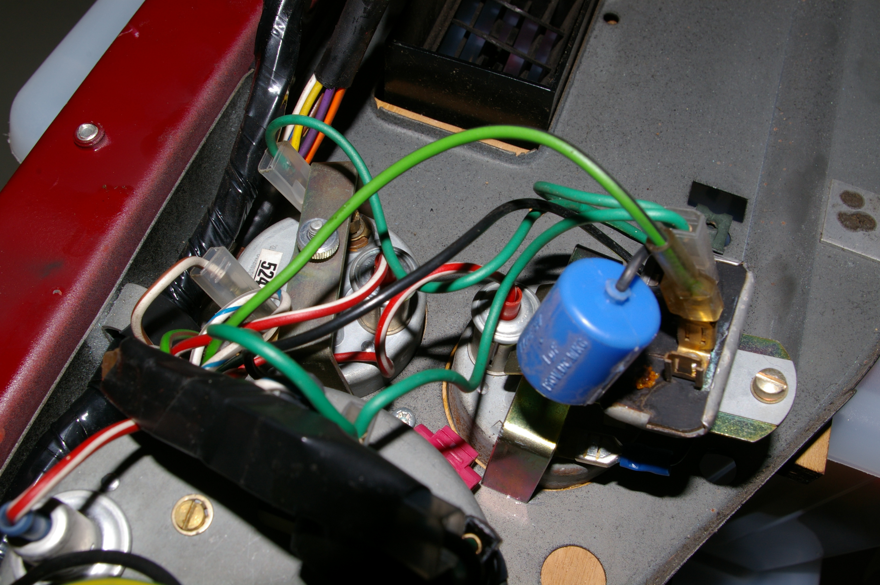
And yes, if you don’t want to pull the crash roll access is from the speedo. Yes again, cw or ccw depends on RHD or LHD. Fortunately, the ROM and Frank know which way. Finally yes, they have an awful tendency to bind. I used a suction cup to exercise even pressure and rotate.
If your problem really is the connectors I made up a sketch while I was in there. The sketch is pretty much self-explanatory; the blue “tongues” are ground connectors. Wire colours are indicated in German - sorry for the inconvenience.
Anschluesse_Instrumente.pdf (388.9 KB)
The voltage stabilizer has one double wire sitting on one of the twin spades in dark green. They lead one to one spade of the lower, one to one spade of the upper small instruments. The other wire is black and leads to a groud connector. A light green/black wire is sitting on the other of the twin spades. It comes from the wiring loom.
Good luck with your quest to find the wormhole to the parallel universe! Maybe our parallel universes are connected …
Jochen
75 XJ6L 4.2 auto (UK spec)
Thanks for your help. I have a USA jaguar xj6 1977 I removed the piece between the tach and speedometer giving me access to the spring round the speedo head. I used a pair of pliers to remove that spring. It was tough but I pulled it off. Eventually I lay on the floor with my feet on the seat and my head resting on the brake pedal. Then I was able to reach up and persuade the speedo to let go.
So now while I am there I reached up and removed the knurled circular nut from the back of the volts guage and pushed the guage out. Back in the seat I found that the wires to the volt guage and the voltage stabiliser were very short and to get the guage out I had to use pliers again to bend the attaching piece for the voltage stabiliser to get both out of the circular hole. Finally I got it bent enough that I could get it and the guage out of the dashboard. My problem is, as I removed the guage and voltage stabiliser, due to the short wires they all pulled off. Now I don’t know which wires go to which place on the guage and the stabiliser. The picture you sent has the big blue resistor , I think it is called ,blocking any view of what wires go where on the new voltage stabiliser and the guage.
I have a S1, so can’t help with the layout. But an alternative approach would be to simply consider the function and wire it appropriately. That should wind up similar if not identical to the original configuration.
The IVR has an input, ground, and output. Ground is provided by the mechanical attachment of the device’s case to chassis ground.
The input gets 12V from the ignition switch. The input spade is duplicated, so the second spade is a handy place from which to power something else that wants ignition-switched 12V–like the Voltmeter. Note that the voltmeter has nothing to do with the IVR itself–it could pick up its 12 from anywhere.
The output [which a pulse-width-modulated waveform switching between ground and (nominal) 12V, such that the time-average is 10V] feeds all regulated instruments. On a S1 this is fuel and temperature gauges (but not OP, voltmeter and clock). Because this output is a switch contact (like the one within an SU fuel pump) a capacitor (not resistor) placed between it and ground improves contact life and reduces AM radio interference. The output also has a dual spade connection; one evidently supplies two gauges, while the second supplies the capacitor.
Hope this might help. IMHO.