I have an unsolved high beam problem on my XJ40 Daimler MY 1992 VIN SAJDKALD4AK657378 with normal square European lights.
Both headlight is working fine at low beam but when I change to high beam the left high beam is not working while right high beam is working fine.
All other electrical items seems working normal.
All other electrical items seems working normal.
When I open the left front realay and bulb failure module and mechanicly operates the left high beam relay the left high beam lights up. Conclusion: electrical relay operation is not functioning.
Can I power the relay with a 12V from any other source to check operation? A normal 12V battery charger? or must it be a much weaker voltage.
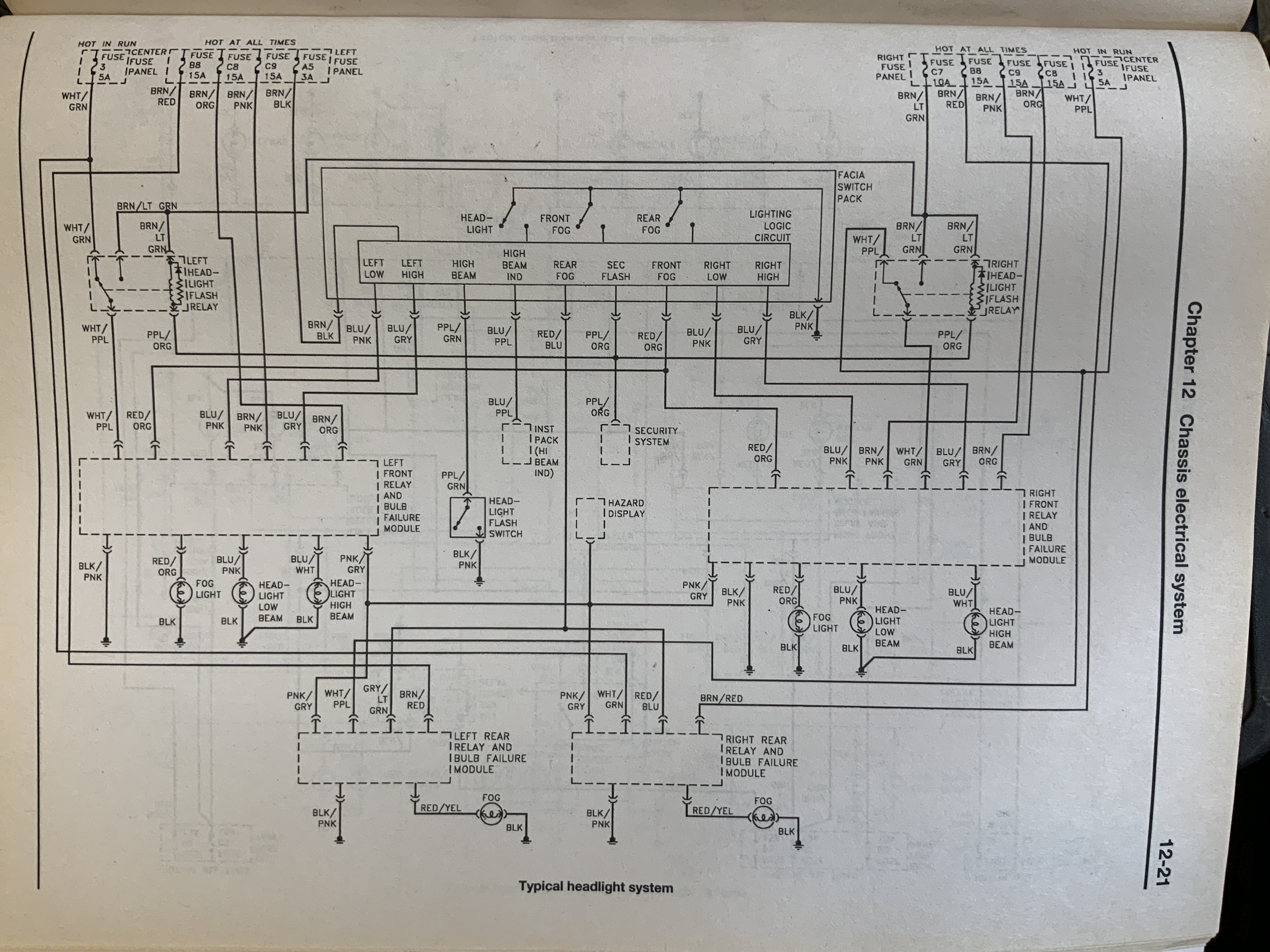
Has anyone a solution for my problem. The Haynes handbook only seems to shows a general layout "Typical healight system. Has anyone a solution for my problem. I think I also need a circuit diagram för MY 92.
Lightning Logic Circuit unit shows no obvious defects.
Well, I checked all the diods and they are fine. Couldn´t see any dry joints on either side of the pcb,
Is thera any special things to look for or to mesure?
Does the relay get a signal?
You can operate it by hand and it works, so either a relay (coil) failure or something in the PCB that is after the point where both high beam relays get their signal from. I would guess 12V and run through everything with a voltmeter. Maybe even a small test lamp.
I wouldn’t try powering it directly.
Yes, the relay lights the high beam when forced to engage the circuit manually (pushed by by a plastic pen).
Du you mean that I can use 12V from an extern wire to check which leg on the relay that operates it? and than follow that wire to the broken point?
No, I wouldn’t try that. I would worry about frying something. But I would look for voltage at the coil of the relay. Multimeter woulld be the best way.
If you have voltage, I would put in a new relay (likely a standard type) and if not, look for dry solder joints and hope to find one.
I agree to that. I am also afraid of frying some circuit.
Do you know of a source for a circuit diagram specific for MY92?
When measuring the voltage of each pin in the round black connector it is not the same on left and right side. And wire colour marking does not 100 % match the Haynes handbook circuit.
I don’t, I never had an XJ40, but I think this can be figured out.
There is of course
a signal from the stalk to the board, where the relay is actuated
and then the current passes to the lamp via the failure unit.
Is the round plug in 2.? Then it shouldn’t be a concern since we know that 2. is working (from the relay, as you found out).
If it is before the relay, in 1., assume relay and board to be working.
I would think that working backwards there must be a point in the circuit 1. where, after the stalk, the signal splits up. Left and right beam have individual relays, correct? Where is the other one, where is the signal split in two?
The “relays” in the bulb failure modules are NOT replaceable units. They are soldered into the boards inside the bulb failure relay modules. I have repaired these modules by resoldering suspect solder joints. To find these bad solder joints sometimes requires a VERY strong magnification. Another option is to purchase another used relay module off ebay or similar. However you are not really guaranteed to get a 100% working module that way either.
Are you located in the USA? If so perhaps you might want to consider shipping the module you have off to an expert top take a close look at the boards.
Hi David and sorry for the late reply.
I have now handed in the car for winter storage so I can only continue troubleshooting this spring.
I think you are right that I should look for the point where the right and left are divided. It looks like there is a difference between the Haynes circuit diagram and the color code of my circuit - do you know where I can get a current circuit diagram for a MY 92?
Hi Steven
I actually got a used BFM and tested but without difference.
Checked the circuit board carefully but saw no cold solder or other faults.
I think I need a better circuit diagram than in Hayne’s manual.
Well, I got the same picture but its not identical to my colour coding.
Maybe I should try replacing my Lightning Logical Unit (if this is the place where left and right relay signal is divided ?)
If it was me, I would go to the plug and temporarily switch the high and low beam wires and see if the fault moves too
Safer: get a test lamp and add it to the plug, connect the other end to ground, compare what happens at the other side. You can now spend all winter trouble shooting, or if you have access to the storage you can figure that out and then spend the winter hunting for a new part. Good luck either way, I hope you can figure it out without too much hassle!
Thanks Mike - Your circuit diagram is different from the Haynes handbook and might match model year -92.
I will check my photos and the real thing when winter is over…
Guess what - Problem is solved!
After comparing both sides and the power in the connector before the Bulb Failure Module I found that one wire was dead. Using a 3M Scotchlok I connected an parralell wiring from the LCU feeding the BFM and giving power to the relay operating the headlight.
Hard to find and easy to fix.
Thank you for all these helps. I have I guess similar problem with french XK40 1993/09 VIN 680716 with square lights
when connecting the battery the right high beam is permanently ON . The left one remains OFF . The purple indicator is ON
I cannot find any soldering pb on the PCB (seems to be the same module than the Johan ones)
I will carefully check cabling and may be Lightning Circuit
Welcome to the forums.
First thing to do is swap the BFM’s side to side to see if the problem stays or travels with the BFM. There are small relays in the BFM and the HB may be stuck closed.