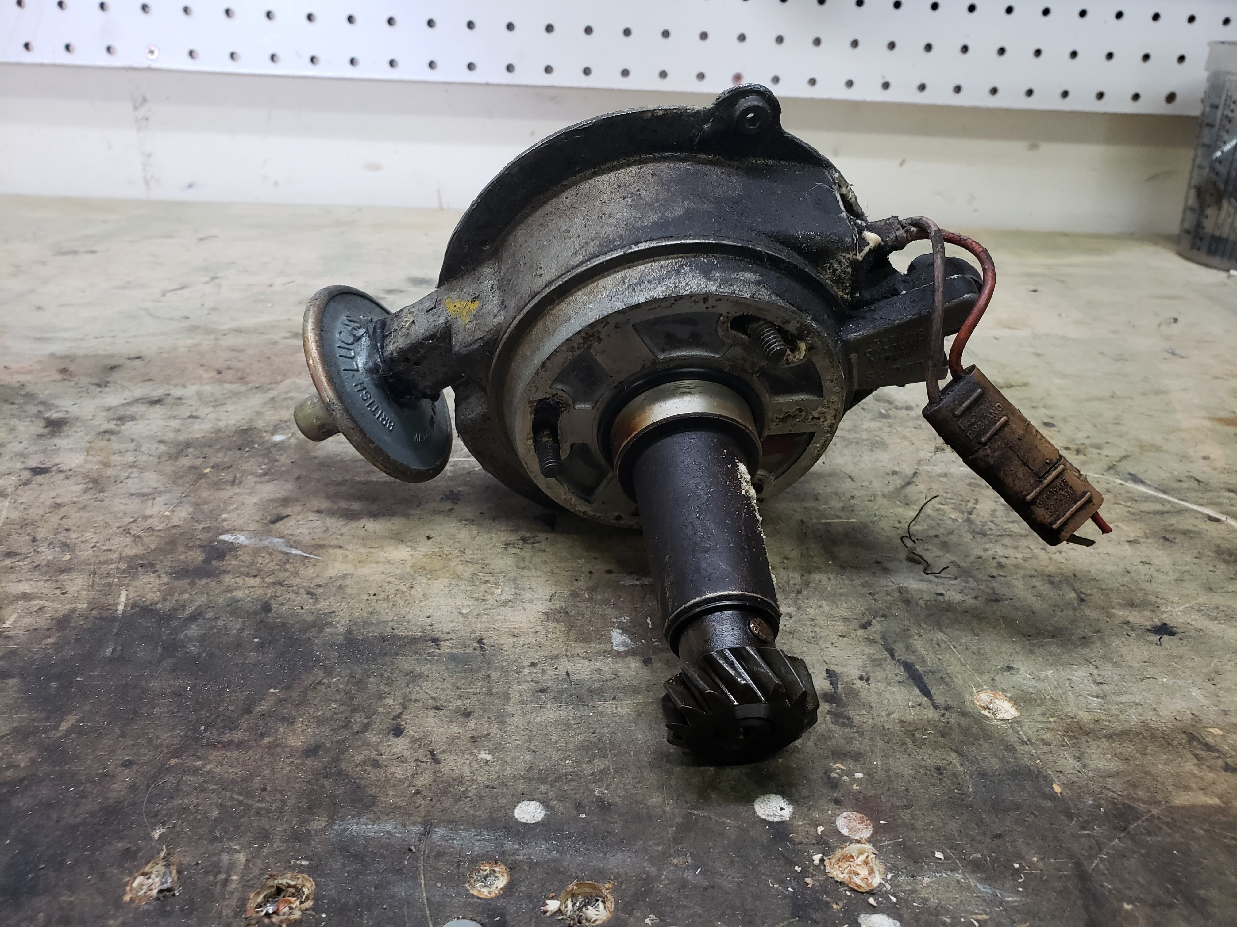
Hello everyone, I just picked up a Lucas distributor from a car out of the junkyard for $35 bucks! I am going to rebuild it and use it on my project V12 so I can just control fuel with an MS3. I had a few questions on parts. does anyone know where to get seals for the ball bearing? or a new bearing with seals on it or where to get the original DZB105 rebuild kit? Also is anyone interested in me modeling the “thingy” in Fusion360?
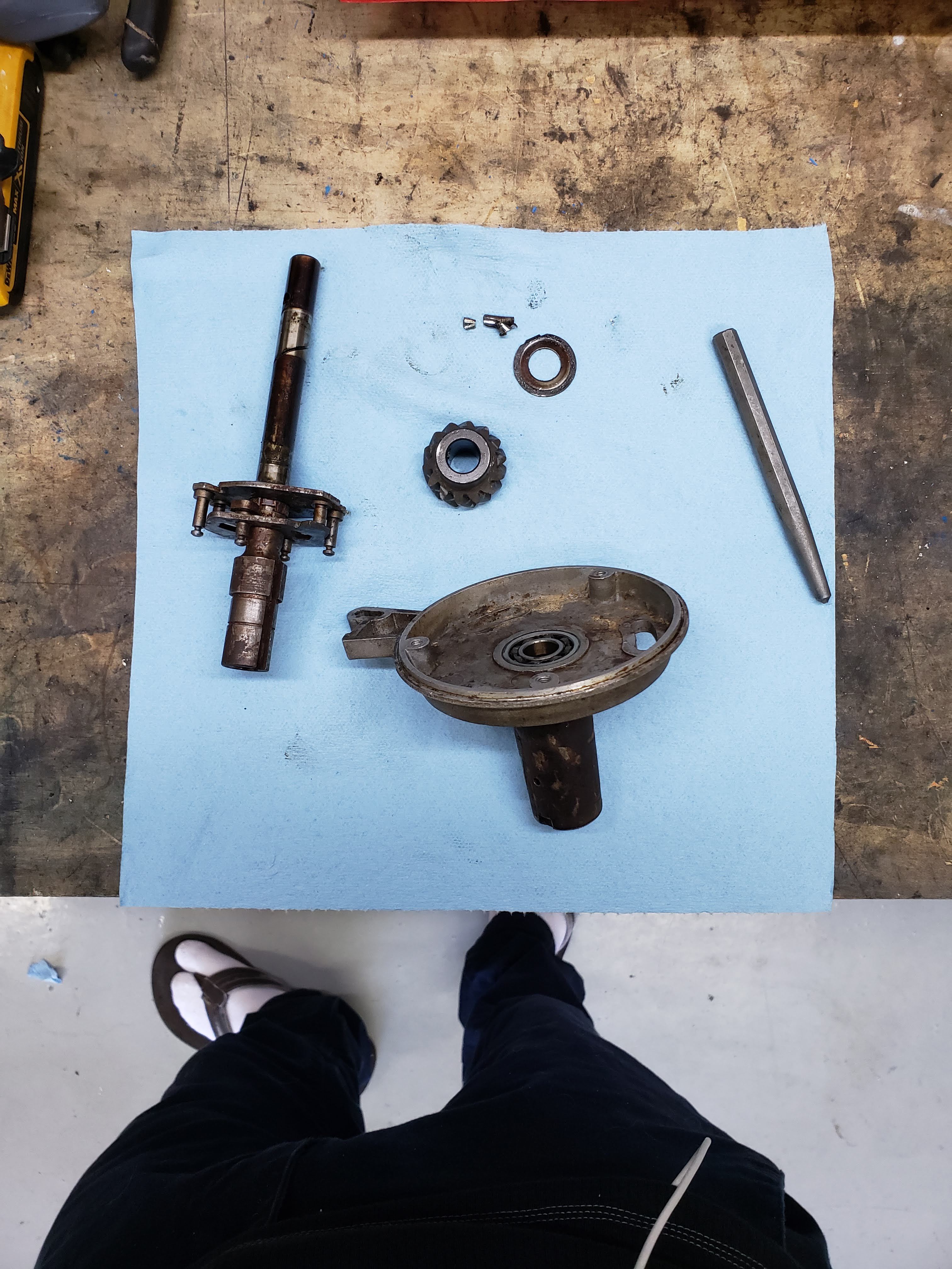
EDIT: also anyone know where to get the thrust washer with the tang between he gear and body. I managed to snap the tang off accidentally
Kirbert
(Author of the Book, former owner of an '83 XJ-S H.E.)
2
SOP is to machine the base to accept a standard lip seal instead of that oddball thing it came with.
It’s easy enough to replace the thingy with a flat washer, so I doubt if anyone will care for a reproduction.
That’s what I did. Turned out really well and can be easily serviced later if needed. Also used sealed type bearing. I used a simple copper washer instead of thingy. Was thinking about printing it as well, but it appeared that simple copper washer workd just fine.
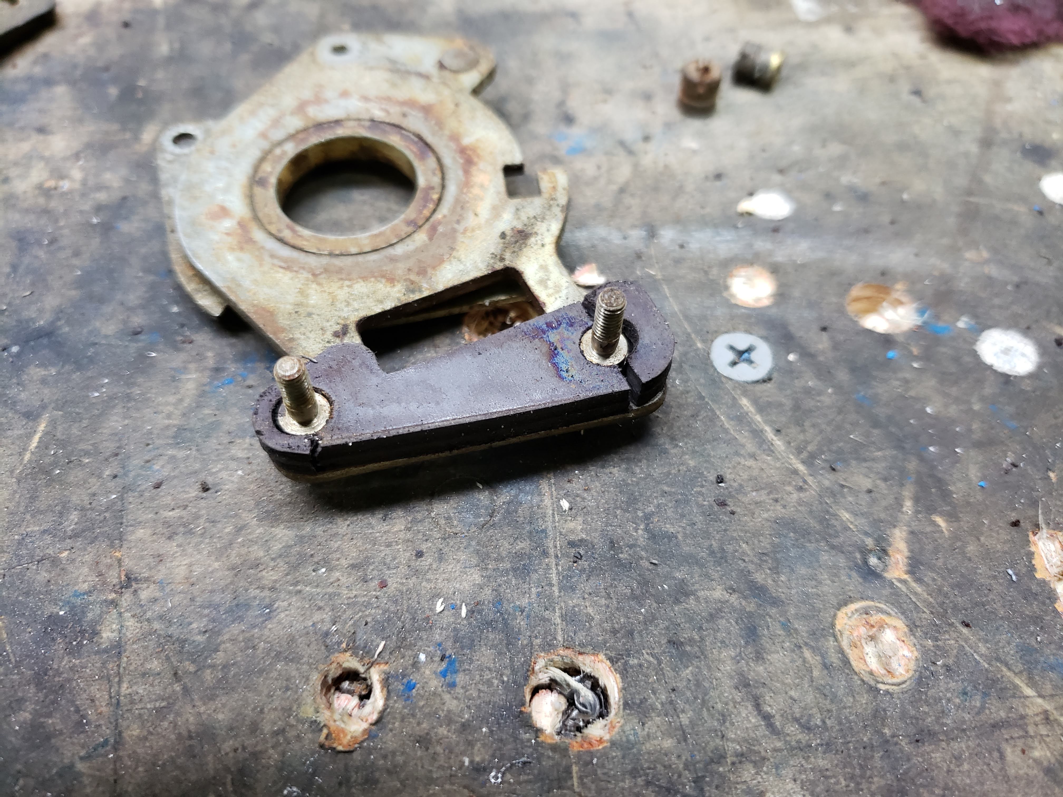
Cool thanks for the reply’s. I am having a hard time finding a thrust washer with a proper tang. anyone know if I can substitute it with a thrust washer without the tang?
Kirbert
(Author of the Book, former owner of an '83 XJ-S H.E.)
5
I dunno about no tang. Presumably the designer wanted to ensure that the motion was between the gear and the washer and not between the washer and the housing. Letting it spin might result in excessive wear on the bottom end of the housing.
There might be other ways to do it, though. You could use a simple thrust washer and install a flush head screw through it to keep it from spinning, if there’s enough meat there to thread a screw into.
I was thinking something like this might work just fine, either that or one made from PTFE. I cant seem to find any thrust washer that comes close to the design of the Jaguar one.
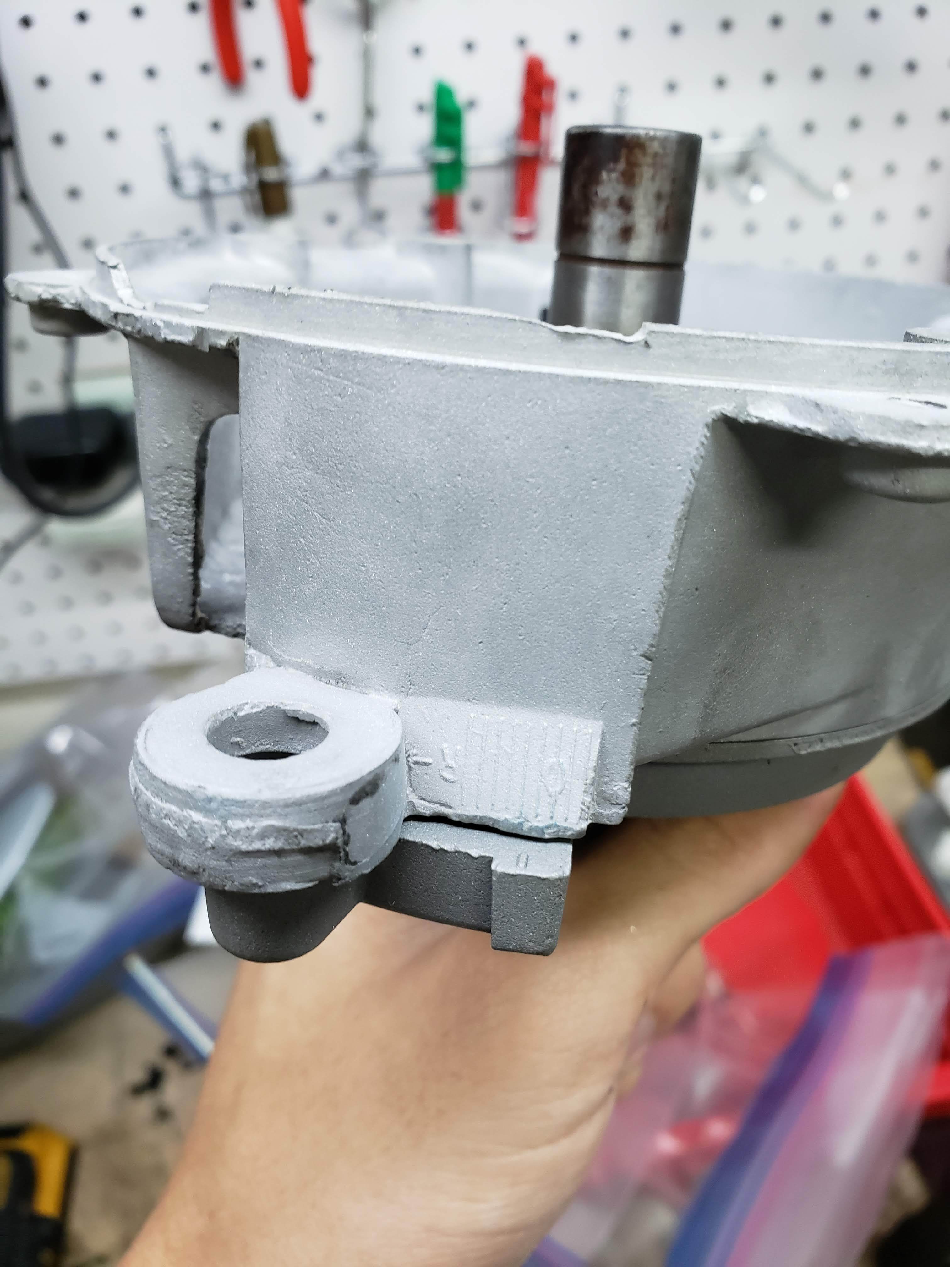
Here is some progress I have made. This is my first time using a sandblasting cabinet and it’s really cool to have now. It makes cleaning and prepping parts sooo much easier. I looked at the ball bearing and have determined that it is still in good condition and i’m going to reuse it.
I would still recommend replacing the bearing with new sealed type.
Bigger problem usually is the shaft seal below the bearing which is usually hard as plastic.
I fully intend on doing just that, but since this is my first time tuning fuel injection myself self I want to make it as simple as possible. once I am comfortable with the fuel part I’ll be adding 6 coils on wasted spark.
That will be a lot of extra job as you will need to re-tune it when you change over from dizzy to wasted spark… Running wasted spark on my 2 V12 engines, one on a MSII and the other on a MSIII. If you can tune fuel you can do the ignition as well, to get full power you will need a dyno in the end
I was disassembling my magnetic pickup when I noticed that the magnet seen in the picture is split at both stud points. What exactly does that magnet do and will it not function properly in its current condition? I would assume it would work just fine right? does the magnet act as a ballast of some sort?
Kirbert
(Author of the Book, former owner of an '83 XJ-S H.E.)
15
Just take those little end pieces out and toss them. Pickup will work just fine with the one larger center piece, and you don’t want those little things to come loose and start bouncing around in there.
I went ahead and bought new pickup assembly because my wiring looked tired and the pickup coil had some wear where PO actually had star wheel touching the coil! Bit pricey though at $120.
But the new aftermarket ones are flimsey metal, the original ones like you have are very high quality. So I transferred the magnet, coil, and wiring to my original one, and it works fine and looks new.
Also, your magnets may have cracked due to PO overtightening.
I neglected to notice that there is timing marks between the two housings on the distributor when I took it apart. Do i set it at 0 degrees? or do I retard it by a factory spec amount? Thanks
Kirbert
(Author of the Book, former owner of an '83 XJ-S H.E.)
19
Those are not the timing marks, they are simply reference marks. If you didn’t note the setting before you took it apart, it probably won’t do you any good.
When assembling, put the crank at 10 degrees BTDC. Set the distributor so that retarded end of the tip of the rotor lines up with the terminal post for 1A. Hence, when the vacuum pulls in more advance, it’ll pull the rest of the width of the rotor tip past the terminal.