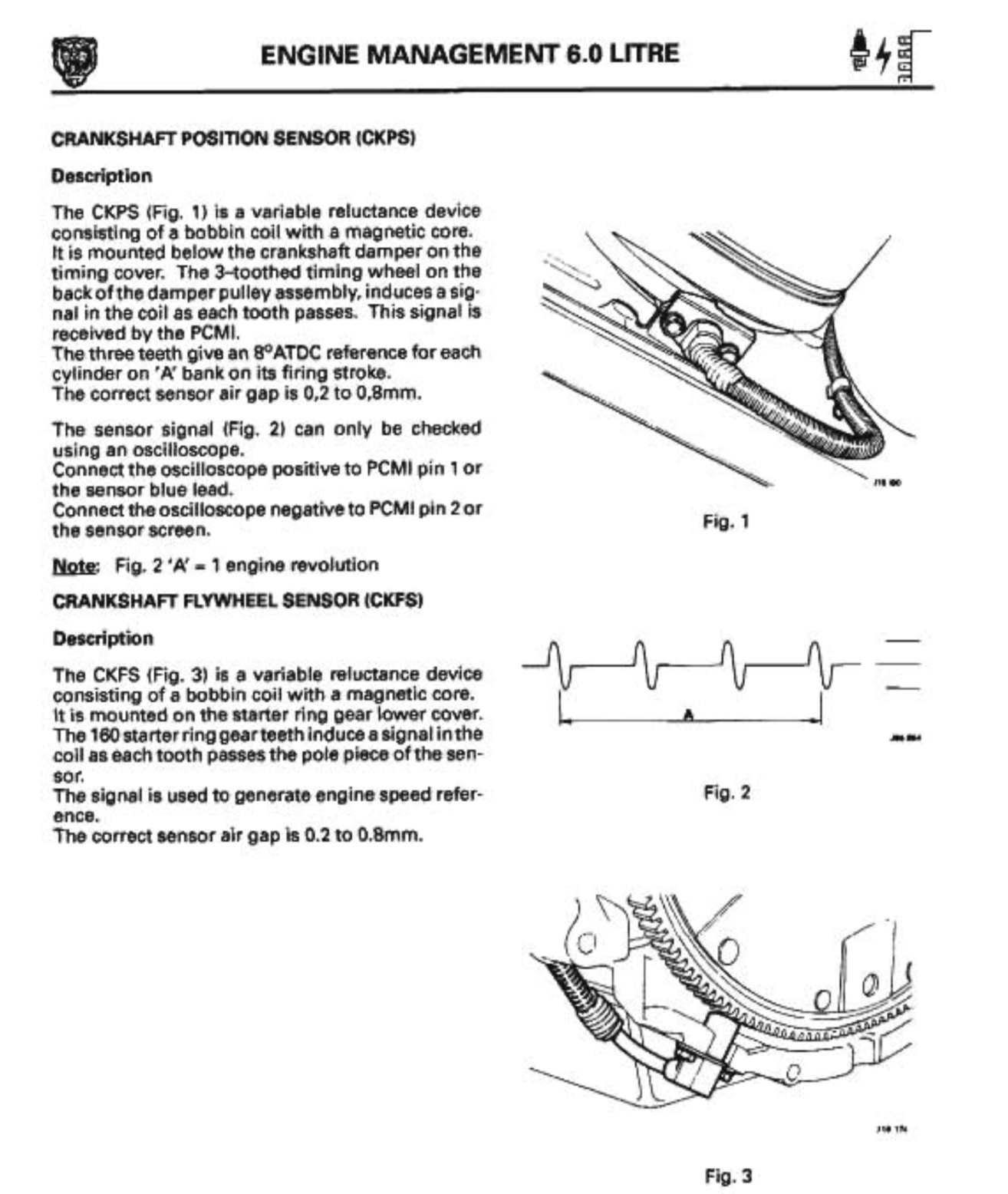
I am working on my '90 V12 Coupe and try to optimize (minimize) my idle stumble. I am currently investigating the Crank Position Sensor and the Flywheel Sensor. I studied the archive of this forum and read through the “Electrical Guide” but can not find a reference to the correct signal wave form of each sensor. I am seeing a square wave on my CPS and a sine wave on the Flywheel sensor. Can someone confirm that this is correct and perhaps provide me with the correct signal data (amplitude and frequency - I know: frequency is engine speed related) or a link where I can get the details?
Much appreciated!
Stephan,
Do you have a copy of the Jaguar XJ-S Repair Operations Manual (ROM)? I found that Crankshaft Position Sensor (CPS) waveform in that document a few years ago when I restored the engine bay of my wife’s 1990 XJ-S convertible (5.3L V12 with Marelli ignition) and had some problems getting the engine to run afterwards. A kind neighbor, who is an electrical engineer, came by with his oscilloscope and verified that the CPS was working properly. Later I discovered that the recently serviced fuel injectors were all stuck and that caused my no start problem.
I have the ROM but it seems (at least from the Supplement description) that the waveforms presented - and posted by Steve - are for models starting 1992/6 litre. Now if I can assume that the signal forms are identical to my 1990 model year then I have definitely different results: The crank sensor generates a square wave signal similar to the one shown in the ROM for the 6 litre on page 25 (fig. 9). The flywheel sensor wave form looks on my car like a slightly distorted sine wave. I have to say, though, that I measured the waveform not at the ECU connector but at the respective connectors of the sensors - under load.
Considering that the engine is running on a closed loop mode on idle, the ignition timing is governed by engine speed and engine coolant temperature. Could it be that the idle switch or the coolant temperature sensor are defect? Any experience with that?
I have to mention that the crank- and the flywheel sensor were replaced not too long ago.
No, the screenshots I provide earlier are specifically for a 5.3L V12 with Marelli. Below are the screenshots from the 6.0L manual and the forms are the same.
thanks again. Yes I am well aware of the fact that the diagram in Figure 9 shows a waveform generated by the ECU. My reference to this picture only served illustrated purposes to show that my CPS signal is a square wave signal like that and not a sinus wave as in your reference diagram. Based on Kirbert’s question and your subsequent response: Both diagrams you posted (the first for apparently the 1990 model and the second for the 6 liter) look the same to me. Am I missing something? And as my car starts fine: How can this be based on a square wave signal instead of the sinus wave the ECU needs to see? I will try and upload a picture of the waveforms I get from my car today or tomorrow.
Caps, rotors, plugs, leads, coils, ignition amps – all the same. The sensors have several part numbers in supersession, for example CPS: DAC4606, DAC7240, DBC12507 – but they all default to the same STADARD MOTORS part # PC452.
Therefore, I do not believe there are any changes in the Marelli set-up over the years.
I don’t think so. The systems operate the same way. The sensors and all other components are the same.
For full disclosure – there a many part numbers for the Marelli ECU, but I think the variety is dictated by the number of markets served, types of fuel, cat vs non-cat and other consideration applicable to the engine timing, not to the signal form
Kirbert
(Author of the Book, former owner of an '83 XJ-S H.E.)
9
Perhaps it’s simply that you’re expecting the Jaguar documentation to bear some resemblance to reality.
The CPS sensor uses a three pointed star on the Harmonic Balancer and the Flywheel sensor uses lots of teeth on the flywheel/flexplate. Maybe that is why you are seeing those differences on the oscilloscope. The sensors are identical but what they are sensing are very different.
Paul
Kirbert
(Author of the Book, former owner of an '83 XJ-S H.E.)
12
What are the teeth on the balancer shaped like? Perhaps they are optimal to generate that neat square wave. The teeth on the flywheel are shaped to engage the starter, so the electronics have to put up with whatever they get.
yes, I agree with both of you in regard to the different “teeth” for the sensors. My original question was about the waveforms: Are these waveforms correct? Please compare them with the ROM that Steve referred to: These are different…
At the end, I couldn’t care less about the waveform as long as I can be certain that the sensors do not contribute to that slight idle stumble I am trying to cure (I know I am not the only one).
Many thanks
Stephan
Ptipon
(Ptipon, Sonora, CA, USA, 1990 XJS, Conv.)
14
Gentlemen,
Applying wave and signal theory, I will explain what you are looking at in reference to what the system is set up to do. From the wave forms showing in Stephan’s scope pictorials, #1 & #2, these are readings right at the sensor. Both signal forms are perfect in
accordance with what is required.
What must be looked at is the signal right at its terminus, the ECU. #1 is a classic wave form for a trigger. #2 is a perfect waveform for rpm. By looking at the signal at the terminus, the ECU, one can determine if the signal has been
corrupted or not. Whether it is or is not corrupted is a function of the medium, the coax and the terminus impedance at the ECU. What is required for proper system function is the exact same wave form at the input to the ECU, assuming that the impedance at the ECU is per factory setup
and has not changed or deteriorated. The set up at the ECU input for a given wavefrom/signal is what is important to look at. Assuming that nothing has changed at the ECU, the impedance of the input circuit at the ECU has not changed and is within specification then all that should
happen to the signal is some loss in amplitude but no change in waveform. Then looking at the signal being received at the ECU, one should shake, rattle and roll the transmitting cable from the sensor to the ECU to see if there is proper continuity in the cable. Other than the input
impedance changing which can be assumed has not changed from design requirement then only attenuation of the signal should occur and the fidelity of the waveform should be preserved. Anything other than fidelity of the waveform should be retained other than corruption due to a problem with the
transmitting and the corruption then becomes a function of the transmission coax. A loss in fidelity of the waveform or intermittancy will in fact cause stumbling to complete inoperation of the engine which then can be attributed to the sensor or the cable of transmission. Both sensors
are showing that they are properly operating. The only other cause will be due to some intermittancy in the cable or some extraneous signal pickup from outside of the cable which wil also be due to a problem with the cable. Once again assuming that nothing has changed in the circuitry of
the ECU, if corruption or form deterioration of the waveform is being introduced through the cable of transmission or something external to the cable of transmission then, one can assume the transmission cable has a fault.
If you have any further questions, please ask. And do an
inspection of the waveform(s) at the ECU to get a definite as to whether the waveform at the ECU is proper for correct operation. Don’t forget to somewhat aggressively shake rattle and roll the cable to make sure that cable integrity remains proper for proper ECU response and action at all
times and circumstances.
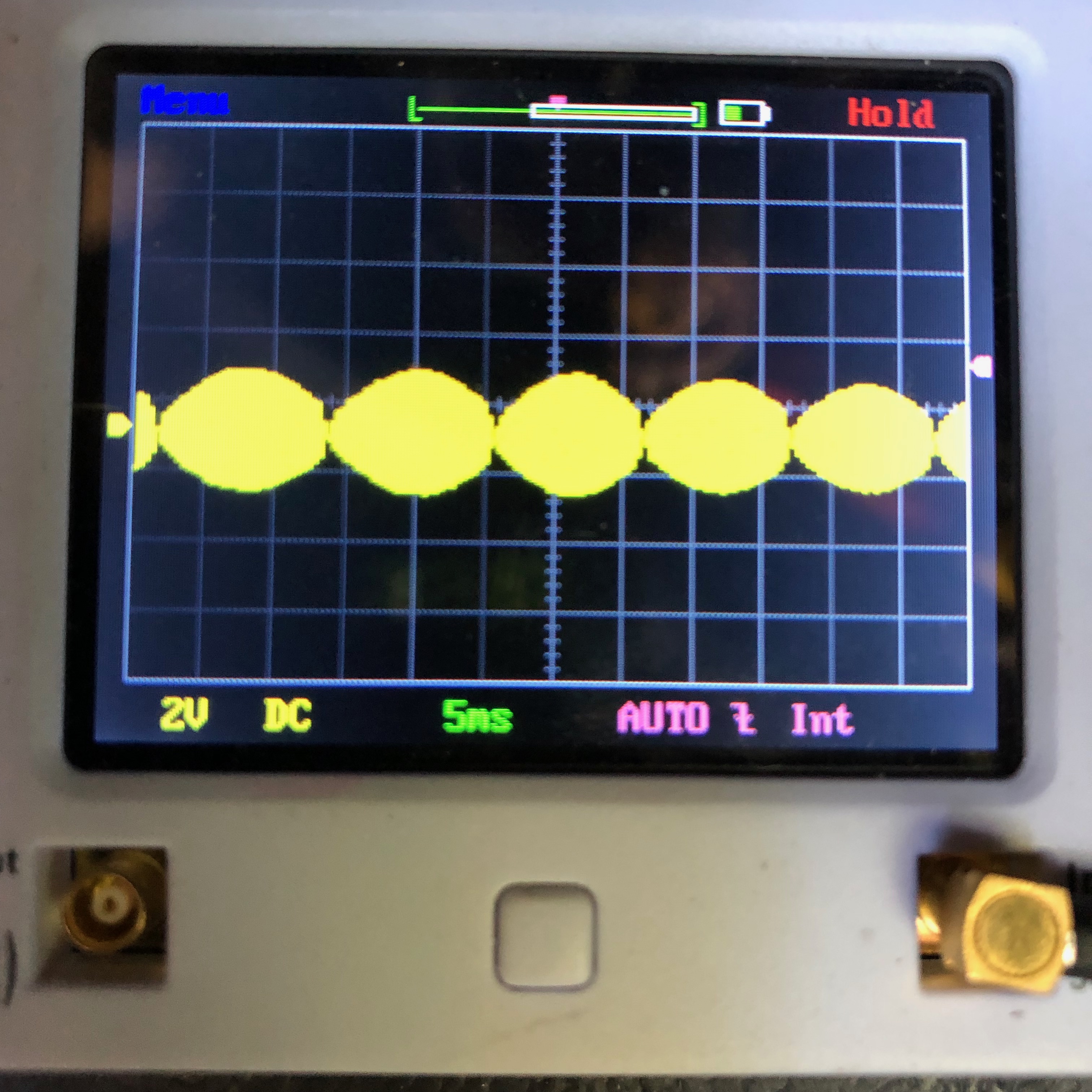
I was able to check the signals at the ECU. Here are the results:
image is CPS signal: Different to my last post, perhaps due to a grounding error (?). I confirmed to have the same image at the CPS connector (next to A/C compressor).
image is flywheel signal: Blurred, was not able to get a better image.
The CPS signal alters in amplitude, perhaps related to minor distant deviations between the “teeth” and the sensor, but otherwise stable.
The flywheel signal “wanders” a bit. I also noticed a very slight up-and-down in idle speed. The ECU-out signal to the EFI wanders in sync with the flywheel signal.
So I guess I can rule out the sensors as being responsible for my idle stumble. I also ran temporary wires from the sensor connectors to the ECU to eliminate any issues with the connecting cables and connectors. Signals are all the same and engine behavior did not change. CPS signal is polarity sensitive, flywheel signal is not.
Any further suggestion?
Thanks
Stephan
Ptipon
(Ptipon, Sonora, CA, USA, 1990 XJS, Conv.)
17
Hi Stephan,
Looking good.
#1 picture says that there is some inductive load phenomena about the circuit from sensor to ECU. Typically it’s just high impedance, no capacitive or inductive electrical component. Could be caused by no grnd at all.
#2 Also fine. If your scope has an internal sync function you can eliminate the drift to the right and left.
#3 This signal is ideal at sensor and at the ECU input
Did you do a shake, rattle and roll to see if there were any intermittants? Just a momentary blink of the signal showing on your scope is a sign that there is an intermittent loose connection which would be a stumble in the rpm of the engine under running conditions.
I bypassed all cables and connectors starting from the sensor connector up to the ECU by means of a separate cable. The issue remained the same: light stumble on idle. Hence my conclusion that the root cause is probably not the sensors. I am currently looking at plugs and ignition cables.
BTW: I recently had a similar phenomena with my 95 Mercedes S: The culprit was the CPS.
Thanks for your feedback and the confirmation.
Stephan
Ptipon
(Ptipon, Sonora, CA, USA, 1990 XJS, Conv.)
19
Great. Did you do the shake, rattle and roll? The only way the CPS will go bad is an internal broken or intermittent lead/hook-up and of course after that, the external connections and cable all the way back to the ECU. There are no mechanical or moving parts in the CPS other than manufacturing connections that will ever go bad.
sometimes when looking for an unusual idle stumble , i have closed the plug gaps about .005 thou.
if it helps i start looking at ignition probs. hey ya never no until you try!
ron