Two things about the wiring look questionable.

I have a black cloth covered wire, which I think goes to the switch, which also has black cloth, and in turn does the ground (earth) connection when the lid it opened. Broken or cut long before I got the car in 1969. The lid hinges were all broken back then, maybe that did it. Ok I can deal with that.
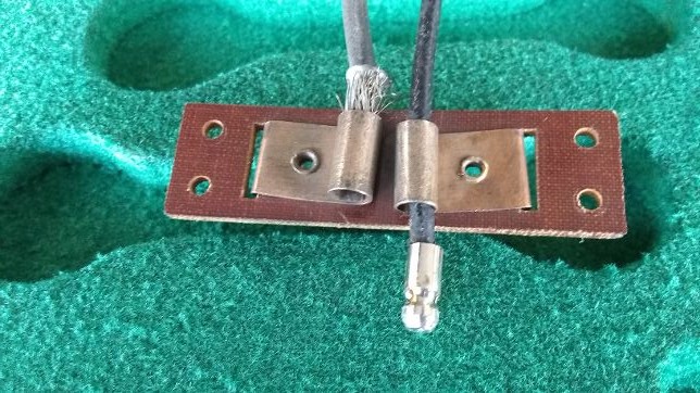
The other wire, also broken, must have presumably gone to the red/green cloth covered wire in the boot wiring harness. But it is not red/green cloth, it is thick black rubber and very flexible. Nothing like any other original wires on this car. I wonder why?
The ends are split cones with wire strands wrapped over on the outside, not soldered bullets.
I have these same split cones on the fog lights.
Is there some reason Lucas chose to use these split cones here, rather than soldered bullets?
Answering one of my own questions.
The loops in the bulb chassis are bigger to take the split cone end.
The bullet end passes right through.
That’s weird.
This was a standard Lucas method Rob, until the spade type superseded it in about the late '60s or thereabouts. I expect it was economical at the factory and certainly easy at the maintenance end. No soldering needed, just a bit of insulation stripping then folding the strands over. They seemed to be used for the low current devices only, not in weather exposed areas, and the soldered bullets elsewhere.
It works quite well but the bullet can’t be substituted for the sleeve because of the diametrical difference in the sockets as you’ve discovered. My '65 car uses both but a '69 car I had only used soldered bullets or spades. The sleeves are available from a few suppliers and it is worthwhile having a few spares in your kit.
Ok thanks Peter. They were rather corroded before I cleaned them up, even though being inside the tool tray lid. I decided to replace both wires with a red and a black, and soldered on the split cone ends. I’m also adding a pair of inline disconnects which can be reached by pulling up through the tool tray, just in case the lid should ever have to be removed.
I wonder which was invented first, the split cone or the soldered bullet.
I guess Lucas was going through a period of development in wire terminal ends. The grounding switch has a side ring terminal which is soldered.
Most of the harness on Mark V is soldered bullets or grub screw sockets.
My '38 SS seems to be all grub screw sockets, no bullets that I can recall offhand.
I have added snap connectors into the circuits for the numberplate panel and the spare wheel door, which means I can remove either one without disconnecting any wires.
You should find unattached split bullets will slip into the sockets without any grip, and can almost fall out, as they are dependent upon the interference grip provided by the folded-over wires. I have seen some sockets squeezed smaller to accept the standard soldered bullet but they become oval, only gripping on the sides, or sometimes develop a crack where bent.
Just a bit of humour, it seems odd that a lamp was fitted in the tool tray but none in the boot. When at display days, I explain this away by saying that it was expected in those days, that cars would always break down and if at nighttime, it was important to see which tool you were scrambling for. As a matter of interest, I have added a boot lamp. It is mounted almost out of sight on the boot roof and operated by a plunger switch fitted into the hole in the locking bar striker block.
Ok I have good tight engagement with both split cone connections and more confidence in them since I also soldered them.
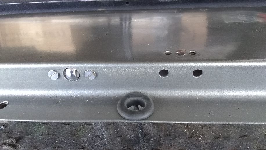
Now for the next thing. I went to put in the switch, and the body doesn’t fit through the hole, so it has to go inside the rim like this. It really doesn’t stick out very far. I presume it must be enough, but it looks odd.
Then there is another odd thing, each of the hinge screw hole pairs has another pair of holes near them which are not used. I wonder what was going on there, perhaps they had planned on some different hinge and then changed their minds.
No light in the boot but a light in the tool compartment is funny, but it was a different time, different people. These days most people can’t even change a tire, they call a service truck.
Those extra holes are certainly a curious addition. Factory or previous owner? But why? Maybe to try and make an alternative hinging system in a past time when the hinges were either not available or prohibitively expensive.
I think the switch needs more projection than what I can see. From memory when I did mine a decade ago, you should find it is adjustable using the locknut system on the back. There are two flats on the plunger to hold it with a small spanner. It does not need to project far, but enough for it to push back about 3mm when the lid closes.
The other thing to check is the insulated connection at the wire eyelet. As it is an earhing switch, the wire and eyelet must be insulated from the stud otherwise it would be in constant contact to earth. There is a special insulating washer fitted to isolate the eyelet from the stem, but to still make contact with the back of the switch body when the plunger returns. As it was a long time ago, I can’t recall the details but seem to remember it would be difficult to replicate this if you don’t have it.
You described it correctly.
I took out the switch and I saw that to loosen the nut would make the ring terminal flop around on the shaft. The shoulder of the shaft has to pass through the hole in the body, and if it was too loose it might hang up on there and not compress.
In order to loosen the nut and extend the button, it needs an insulating sleeve between the ring terminal and the shoulder, but it must be small enough to pass through the hole in the body.
What I came up with is shrink tubing on the threads, about 1/8" of it.
That looks better.
Surprise - surprise. There are various snout lengths.
For the benefit of others who have still to work on theirs, the photos show the details for the earthing connector eyelet with the contact side and the insulated side; and the order of assembly. Note the extra fibre insulation washer between the nuts and the connector. I think the reason for the double nut is not just to prevent loosening, but so that you don’t need to tighten too much on the softer insulation layers.
Yes, the longer length snout is used with the Mark V saloon front doors, shorter length for the tool lid.
Mine have only one nut, but it is a self locking type, possibly Simmonds Pinnacle or Nyloc.
On Mark V 628166 the tool tray light switch unpressed nose sticks out about one eighth of an inch. The front door light switches unpressed noses stick out half an inch.
1 Like