Does anyone know where to get a proper Tee to connect the brake servo vacuum line to the smaller line that goes to the MAP sensor? Looks like the brake servo is 5/16 OD (3/16 ID?) but the hose going to the MegaJolt is 1/8 ID. Am looking on McMaster but not seeing Tee’s with different sizes.
Theo,
Try looking at pneumatic controls piping suppliers.
Matt
The closest I can find is this:
https://smile.amazon.com/gp/product/B07C54B3DX/ref=ppx_yo_dt_b_asin_title_o01_s00?ie=UTF8&th=1
I ordered a 6 mm X 8mm X 6mm tee for the fuel line to the carbs but it hasn’t arrived yet so I can’t comment on the quality. It’s somewhere between China and here.
I ordered a plastic Tee from Summit, it’s stepped from about 1/8 to 1/4 so I can cut the ends to fit the needed sizes. We’ll see when it arrives sometime this week I hope.
Theo
So I gather you are hooking up the MAP sensor to the manifold vacuum.
I think this means that at idling you will have full vacuum advance which is much greater than the engine was designed to run. It might be hard to get a nice smooth idle.
That is unless you can program the Megajolt to ignore the MAP until the engine is running above say 1000RPM - which I don’t think you can.
I plan to use the carb vacuum port to maintain no vacuum at idle and to use a generous sized reservoir to smooth out the pressure signal going to the MAP sensor.
We shall see
Bruce
Dear Bruce,
Have you thought of simply adjusting the throttle plate a bit… ?
kind regards
Marek
I think that is only relevant depending on the programming in the MJ. Ray Livingston’s kit and ignition maps are designed to use manifold vacuum, so I assume the ignition mapped are programmed for that. I will recheck the EDIS support thread on the UK forum but I’m 95% sure that’s the way it’s supposed to be.
Theo
It will be interesting to find out what you discover about the Ray L. settings.
I suppose that people who have fitted the kit have satisfactory idling.
The thing that still strikes me is that the centrifugal and vacuum advance are independent variables so that control of one will not affect the other.
The MJ does have user configurable outputs that will signal when a selected RPM is reached. Using manifold vacuum, perhaps one could set things so that upon reaching say 1000RPM the MAP could be enabled.
I must think about this
Bruce
Here are the top comments from the UK forum.

The EDIS is designed for manifold vacuum and all the maps are calibrated for it.
Theo
What can I say? Using the manifold vacuum is certainly fine once the engine is off idle.
I can see that the carburetor port is not good by itself because it will have significant pressure fluctuations which can/will upset the sensor whereas the manifold pressure will be much calmer.
It is just when idling that I still have an issue. But then I do have a work-around if I find I need it. Still waiting to get the car out of storage
Perhaps you could post the map you will be using?
Bruce
I’ll probably start with this one.

It’s a copy of a stock 4.2 distributor. There is no advance at low RPM, the advance only comes in at higher RPM and at low load.
In response to Carl – trigger wheel size, refer to a prior post I did on this: 3.8 Mk2 EDIS conversion running on stand
If I were to do it again I would go slightly larger as the room exists and would make fitting the sensor a bit easier.
Regarding vacuum – I’m using the vacuum line for the brake booster and a map that came from Ray Livingston (which was posted somewhere). I blocked the vacuum port on my HD8 and used manifold vacuum based on the same reasoning as Theo…it’s what is generally posted in online support documents. Engine is still on the test stand, so no real-world driving experience yet.
Cheers Tom , great video!
For those who’ve wired and tested MegaJolt/E, is this the correct wiring diagram? It’s from Autosport labs so I assume so.
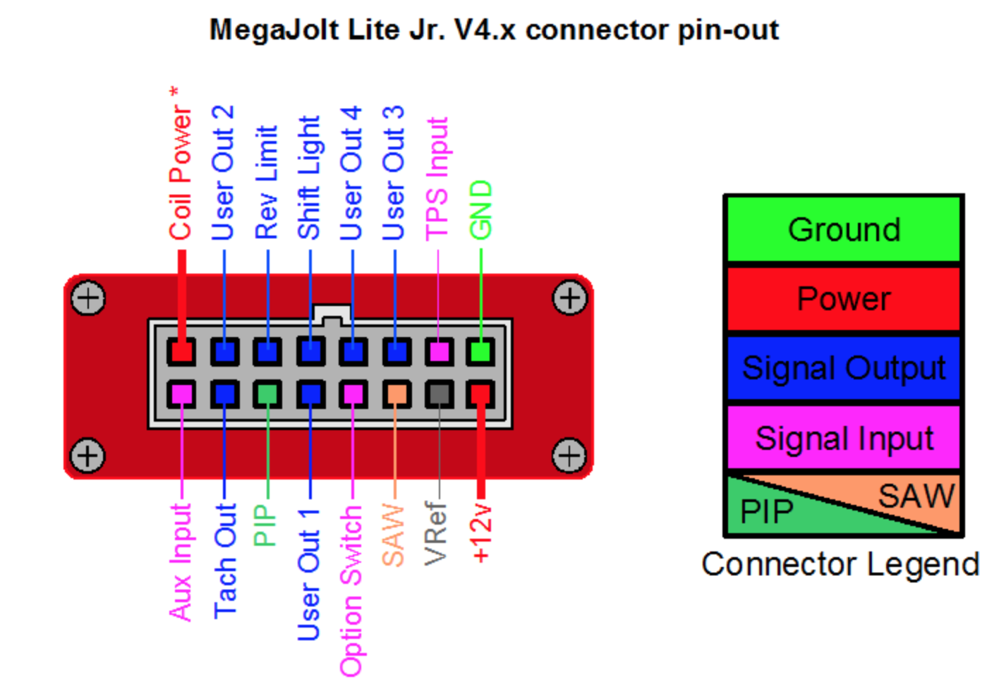
I ask because on the UK forum another fellow posted his wiring diagram, and the pins on the MJ are different.
Just want to do this right the first time! Thanks
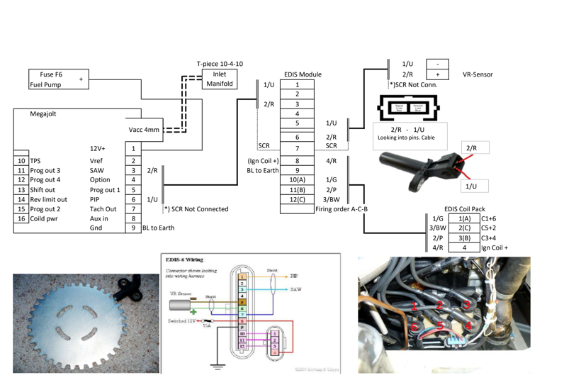
Any thoughts on this @tapped or others who have successfully wired an EDIS? I got my system all set up and it won’t run. I noticed on the diagram above the listed wiring from EDIS to the coil is different from the inlaid diagram from autosport labs. I tried both wiring configs, and neither worked. Anyone able to clear up the proper wiring? I put a timing light on it and also tried with a plug on the engine block, and no spark at all…
Also, another question. I can’t get my laptop to connect. I’m trying to figure that out, but I also noticed when I crank the car the RPM LED flashes a few times and then stops. Turn the car off, back on, crank it and it flashes a few times and stops. Does this mean I’m not getting a good VR signal or maybe the thing is just not configured correctly?
Ugh this isn’t the result I wanted on first start!
Question for @BESM also, I’m trying to compare your initial tests pdf to the pictures of your setup, it seems the coil wiring doesn’t match.
Your diagram shows the pins 10,11,12 crossing into a different order on the plug, while the picture of the plug looks like they connect in order. Here’s how I did mine, is this correct?

Theo – I had some teething issues getting my EDIS up and running and it ended up being two of the coils (of the three in the coil pack) were swapped. So I was still getting spark from the beginning, just in the wrong order. When I wired mine I realized this was a potential issue as various wiring schemes I found online had different wiring diagrams for the coil.
If you’re not getting any spark – I would make sure the coil is grounded correctly. Regardless whether the coils are mis-wired (e.g. swapped like mine), if the coil is not grounded properly I assume there’d be no spark at all.
VR sensor could be a suspect as well…but this is a pretty simple sensor, just make sure all your connections are solid (true for all your connections). Btw, I believe this is polarity sensitive…so if you haven’t already try swapping the leads on the VR sensor.
I followed the Autosports Lab wiring diagram. That’s where I bought the Megajolt setup. I bought mine several years ago…I believe the recently rev’d the design. You may have the newest version? Not sure if the wiring diagram is any different between the versions.
What about your EDIS module? Is that a known working item? I found a new one on eBay (not that that’s a guarantee that it actually works…but it did).
Here’s a pic of my coil connections. Note that I added a ground lead on the lower right hand mounting bolt. I don’t believe I saw anything about it needing to be grounded…I added that because it seemed logical. I don’t believe it’s grounded through the connector. Looks like 12v+ on left and three other wires for the three coils…so if there’s a ground needed it’s through the body of the coil.
Is your coil grounded?

My coil is not grounded… It doesn’t say anywhere that that is needed! I will try tomorrow. I am not getting any spark at all after checking everything 100 times. Doesn’t the coil ground through the plug wires? Isn’t that what fires the spark plug?
I am now suspect of my EDIS module. I got it used off Ebay. According to Autosport Labs, there should be 2.5v running through the VR sensor wires. I don’t have a multimeter but I put a test light between pin 5 + 6 and there was nothing at all at crank over, not even a dim glow. Same at the sensor terminal. But it’s not clear whether this means the sensor is faulty or the EDIS is faulty.