Although it looks OK, I have taken out the fuel tank of my 1948 MK IV 1 1/2 litre in my task to restore it, and I have cleaner/sealant, etc at the ready. Before I start work it would be useful to know how the inside of the tank is constructed and what position or layout any internal dividers or baffles are. Does anyone have any construction drawings for the Mk IV1 1/2 litre tank or photos of a tank cut open? It would help me in knowing how I “roll” the tank during the cleaning out, preparation, and sealing process to make sure I work everything back out of the tank and drain it fully. Thanks
At my lab we once had a piece of scientific equipment that needed a similar inside cleaning. We put stainless steel nuts in it and rolled it around awhile, counting the number of nuts that went in and the number that came out. Then flushed it out with water and then alcohol and checked the amount of dirt in the alcohol until it came out clean. Worked good enough for the science experiment anyway.
1 Like
At my lab we use process similar to that described by Rob. I prefer acetone washes to alcohol unless optical parts are involved (in which case stainless steel nuts are not used). Perhaps I am older than Rob because young’uns use alcohol rinses in the lab instead of acetone these days.
It would be useful to know the internal design and layout of my tank (like the separation “walls” and positioning of the reserve tank, any baffles, etc) as I think this will give me a better idea of how to roll and manoeuvre the tank when I clean it and re line it. I need to get into every iternal corner and space to make the job successful, so any construction information would be most helpful. Thanks
Hello David,
You may consider exploring the tank interior using a boroscope.
If my 1938 tank is similar, I can see the position of the baffles by the spot welds that hold them to the outer shell. There are two baffles or walls, one about 8" from one end and the other about 12" from the other end.
Baffle walls are generally to stop major sloshing around the pickup tubes and level sender when you’re running at half tank or lower on a long curve, so they cover most of the cross sectional area but leave spaces for the fuel to pass under. I guess they don’t care about sloshing in the middle.
The SS tank is rather different to the MkIV tank but David could also look for the baffle spot welds. For info. the 1½ litre MkIV uses the same tank as in the 2½ and 3½ litre MkIVs.
Peter
I have a suitable camera probe John, but I always find it more useful if I know where I’m going and what I’m looking for - otherwise it’s like driving at night down dark country lanes with one headlight on and without a map or knowing where you’re heading!!
As Peter says Rob the MK IV tank is slightly different from your pictures, but I will certainly look for the tell tale signs of the spot welds. Unfortunately with some 70 years of black underseal, gloss paint, and dirt on it I need to clean it first and probably sand blast it to be able to find anything hidden underneath. I was not sure how the “reserve tank” part was constructed within the main tank - am I correct to believe that the two drain plugs under the tank are one from the main tank and the other from the reserve tank? I’ve got to make sure that the cleaning liquids and tank liner liquid I put in goes to every metal surface AND all comes out again (plus flushing out the rubbish).
Thanks
Hi David,
As far as I know there is no main and reserve tank. The main and reserve outlets are simply set at different levels within the same tank. Have you been able to unscrew the filters in the two wells? My tank is the same as Rob’s and may be subtly different in construction to yours. I found it impossible to remove my filters and ended up splitting the side seam of one of the wells by applying too much torque to what is a soft soldered construction.
If you can remove your filters reasonably easily it will give you a better view into your tank.
Peter
Not yet get the filters out Peter, as my first attempt found them so tight I did not want to over-stress them before I cleaned off all the paint/underseal. I will take your note and proceed with care.
Interesting to learn that there does not appear to be an internal divide or “tank” as I’d assumed for the reserve supply, only a difference in supply pipe length. So I guess that selecting the “reserve” lever inadvertently sucks up all the dirt in the bottom of the tank!!
NOTE TO ANYONE WORKING ON A FUEL TANK - even with a tank empty of petrol, make sure you wash it out several times and vent it for some time BEFORE you do any work on it. Even a wire brush can cause a spark that will ignite fumes.
Thanks
BTW Do not attempt any sloshing nuts around in the tank if you are unable to remove the filters otherwise you are likely to destroy their gauze.

Peter
ps Removing the fuel gauge sender may give you the best view into the tank.
I found this reference in the old Service book that came with the car:

It does seem to indicate that there is a dividing baffle between the main and reserve outlets, so I will look for the signs of spot weld marks as suggested.
The pipes don’t pick up from different levels as they are set at the same low level inside each gauze filter. It is important that both pipes insert into the filters otherwise there will be no filtering. It is the baffle that separates the last 10 litres or so by not having any transfer openings that you find in normal baffling. If you poke a spy camera down the sender hole, you may see a baffle with holes, but this is only an auxiliary normal type of baffle and the dam will be further along.
In stating this, there should be no difference in using the main or reserve position on the tap for choice of normal supply as, after drawing from the ‘Reserve’ side (which is the nearside of the tank) first until empty, the switch over to ‘Main’ should continue to provide petrol from the offside of the baffle. In other words, there should be no trepidation in using the ‘Reserve’ first, say by mistake, as you should have a quantity held back on the ‘Main’ side of the baffle. The sender float is on the main tank side (offside) and will record ‘empty’ for this amount only, as the reserve amount cannot be detected by the float.
The interesting thing is, the instructions posted by David above, state that the baffle is offset to the nearside, therefore containing less fuel than the offside, meaning that if you reverse the priority of tap position, when the reserve side has emptied, you should have much more ‘in reserve’ on the main side.
One day I will test this reverse theory - and take a can of petrol to be sure. The reason for carrying extra petrol is that for the baffle system to separate the bottom of the tank as intended, it must be fully sealed to the bottom and sides. If there is any opening, the whole tank will be drained by either tap position and you will not have a reserve. The standard practice in those times would have been to fully solder the joint after spot-welding as there was not any fancy sealing goop around.
I think it is worth each owner doing a run-dry test to check that there is actually a working reserve so that you know whether you can rely on it when you get caught short.
I’ve got the drain plugs/filters out and removed the sender (which I’ve now got working ok) and confirm that it is as you say Peter with baffle separations and pipes droppings down into the filter bodies at equal levels. Not yet got my camera in as it needs to defame for a while, and will inspect to see the location of the metalwork. I guess the tank was the same for UK or export, so the Service Book note about “nearside / offside” is written on the basis of a RHD car.
I’ve done a few tanks by removing all the bits and plugging with plastic bungs, then putting a box of drywall screws (Cheap, and very hard) in, adding some rust remover (Citric acid), then strapping them to a cement mixer for a few hours, then re mounting the tank about the other axis a few times.
It works great, but getting the screws back out can be a bother.
My '38 SS tank is out and I was looking inside today with a flashlight and mirror. It appears that the interior wall located about 7 to 8 inches from the left side has 3 big round holes about 1" diameter at the top, but none at the bottom. There is some sort of shiny black stuff in the seam around this wall, and whoever put it in used too much so some ran down the wall and into the reserve drain pit. It is caked up around the reserve drain plug aperture.
It doesn’t look like a previous owner’s sealing job, because it is only around the seam, not anywhere else. I think it must have been put in when the tank was new. I wonder what that stuff is. What sealant did they have in '37 that was impervious to fuel?
So the reserve really is more or less separate from the main tank. The main tank gets filled when you fill up into the reserve and the gas runs over the top through those 3 holes into the main tank.
And to do a sealing job now, you will need to do both sides separately, or at least think of them as separate compartments when rattling your drywall screws and sloshing your sealant around.
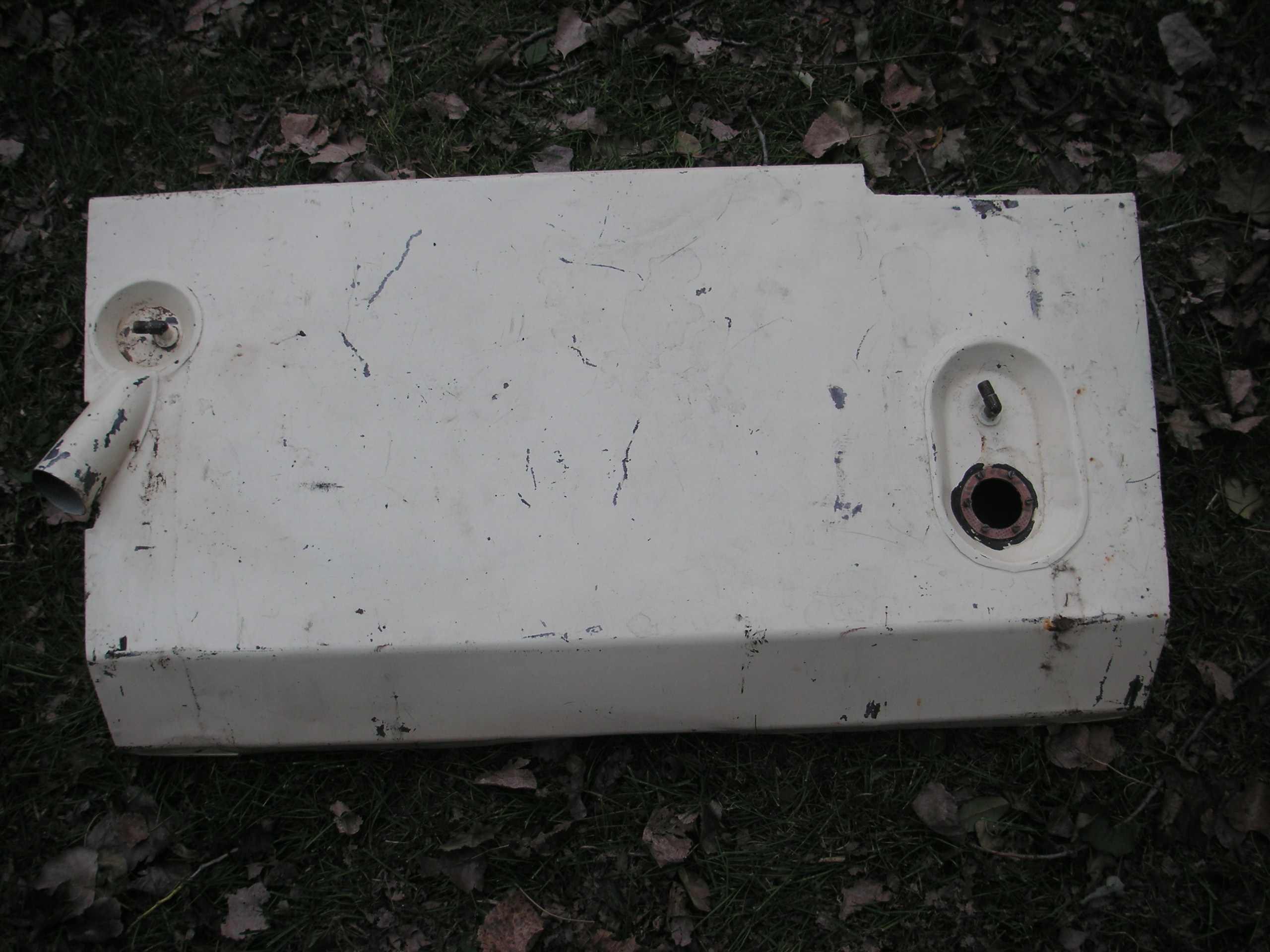
I have taken some internal photos of my MK IV fuel tank:

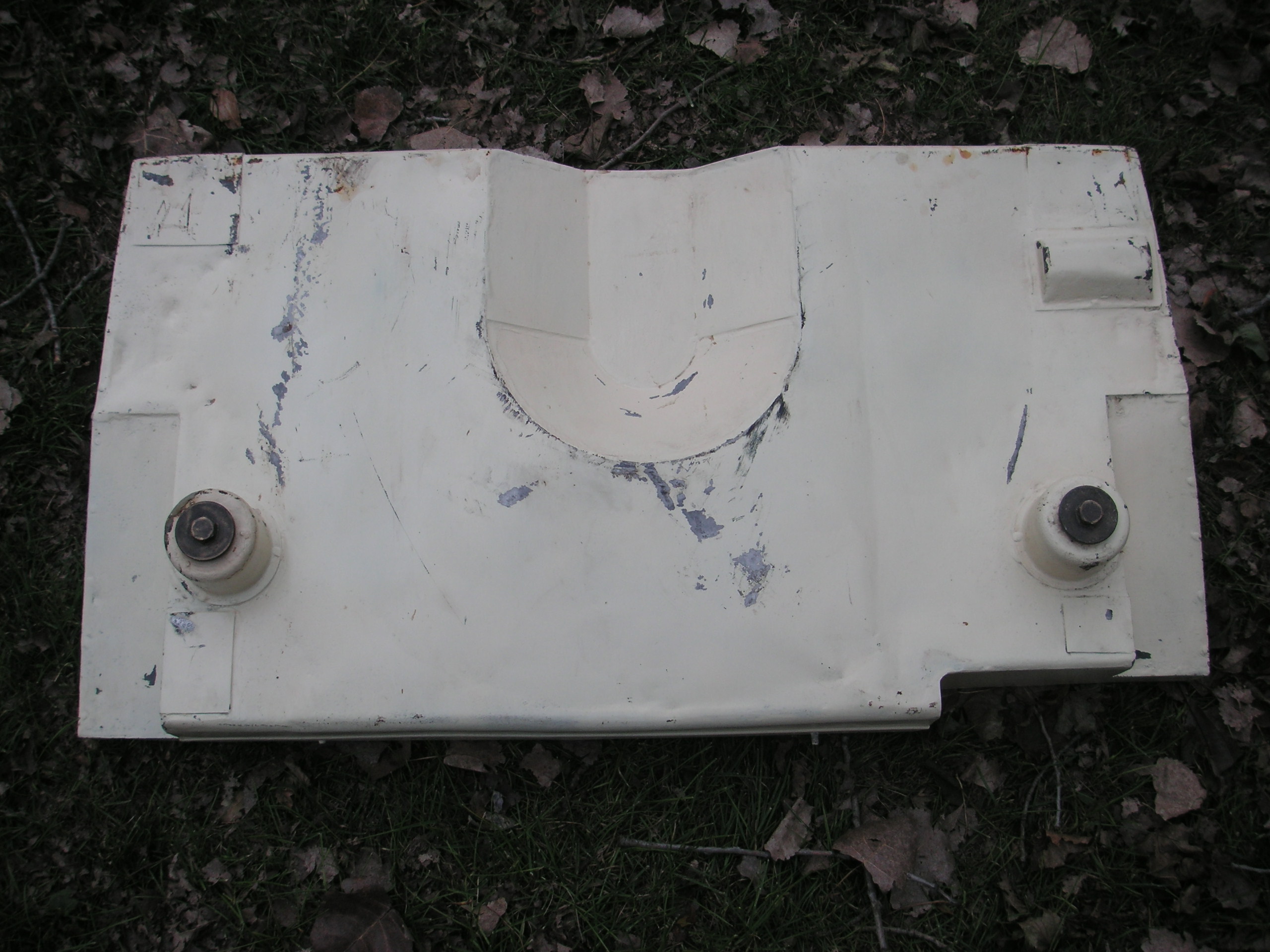
The lower curved edges of the front to back baffles are cut away to allow fuel to pass through the sections of the main tank.
The baffle between the reserve and main tank sections (offset to the nearside) is completely welded to a sealed joint, with a gap provided at the top of the tank to allow fuel to pass over to the main tank side when filling up at the fuel station.

The baffles in the main tank (to stop the fuel slushing around when the car corners, etc) are again provided with a gap at the top (with a turned over box edge) in addition to the openings on the lower sections (as per previous photo)

From the external fuel “switch” (to select main or reserve tank) connectors are provided through the tank wall and these two pipe outlets go to the “drain off pits” in the reserve and main tank sections.

These internal tank pipes drop down centrally into the fuel drain pits, and from the outside is screwed up the fuel filter cartridges to mate with these pipes inside and almost full length of the filter cartridge. You need to make sure these pipes slide into the fuel filter cartridges correctly before screwing in the filters (otherwise you will push up and distort the fuel pipe, and could end up taking out fuel which is not filtered).

My fuel filters were very difficult to get out, and I used an adapted modern strap type oil filter removal tool to grip the round body of the drain pit before exerting pressure in unscrewing the filter nut (thus avoiding the seams or metal twisting out of shape or splitting).

A before and after photo of my cleaning up of the filters (need new seals).
My fuel sender was completely corroded, seized solid, and consequently did not function
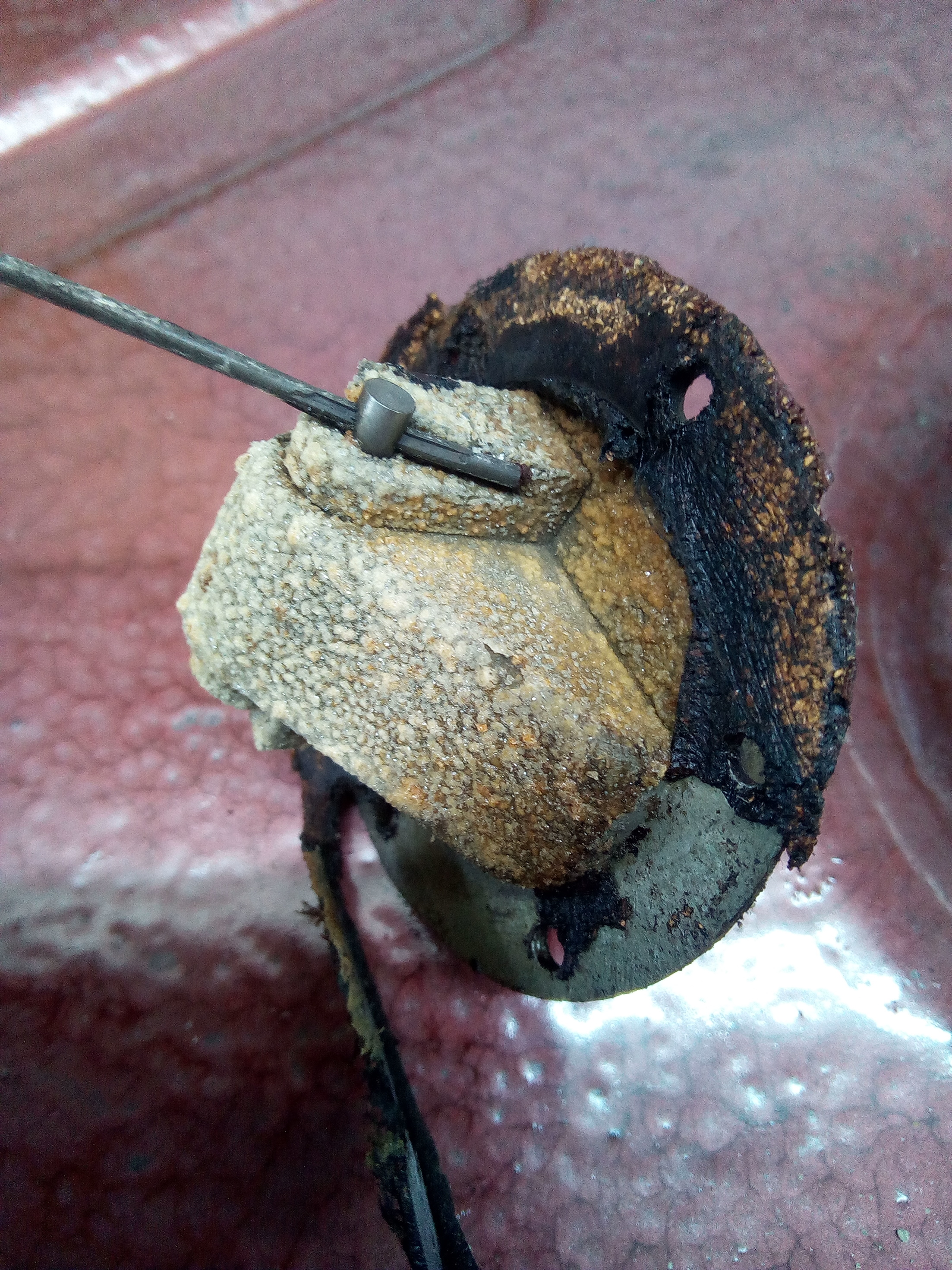
But after several days of careful work it is now fully working OK

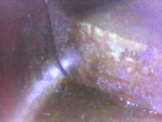
I will now spend some time cleaning out and preparing the inside of the tank, but I was pleased to find only what looked like surface rust on the internal metalwork (be there lots of black rubbish and residue that has collected on the bottom of the tank and clearly not drained out of the filter pits over the years. Once cleaned out I will apply some tank sealer and paint the exterior.
Very interesting photos. Thanks for posting. In my SS I’m not convinced that the baffles are very effective at restricting fuel movement on cornering. I get significant gauge changes on cornering. Perhaps as much as two or three gallons of change from one corner to another.
Peter
Perhaps the baffle design was improved from the SS to the MK IV - on mine there do not appear to be any additional holes in them apart from gaps along the bottom curves front and back. That said I’ve not had the car on the road to go around any corners!!
I think the needle stability on modern cars is somehow associated with a damper built into the system.
I work on the basis that the gauge is likely to be a purveyor of fake news… and so keep the tank reasonably full.