Gentlemen,
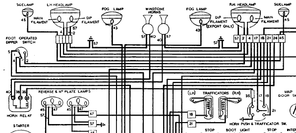
The horns failed on my car recently and I began searching for the cause. I think it was poor connections and a broken wire but am still working on it. The car (Aug 1948) is pretty much original but the horns have been mounted on an aluminium bar beneath the round tube joining the front chassis members. (if I can work out how to add pics I will). The wiring diagram for my late model car suggest that the loom should yield a pair of purple/black and purple wires with one of each going to each of the twin horns.
My car has only a single wire of each colour coming out of the loom and terminating in what looks like some sort of regulator or relay mounted on the bar between the horns. then a pair of black wires coming out of a single output terminal on the ‘regulator’ to each horn. Definitely not in the wiring diagram.
Can anyone enlighten me on the setup and why it is so?
Perhaps this is perhaps a factory modification on late cars that was leading towards the MKV?
And can someone let me know how you attach a photo or three?
Thanks
Darryl Grey
South Australia.
Hi Darryl,
If you are writing in the JagLovers forum you can simply do copy and paste to add a photo. The photo below is from a December 1947 car. A horn relay is a sensible addition but I don’t know that it was a factory addition. I suspect the aluminium bar was almost certainly not a factory item.

Peter
Hi Peter,
Many thanks - I will post in the Forum with pics tomorrow
Cheers
Darryl
Welcome Darryl.
I don’t know whether your relay is factory work or not, but it makes sense, as I suppose the Lucas engineers figured out the Windtone horns were passing too much current through the push switch, and used a relay from Mark V onwards with those horns.
Assuming your horns look something like this:


There should be two wires going inside to the coil terminals.
One is ground, presumably positive, and it even could be grounded inside the horn, although not ideal. The other is the negative, coming from somewhere.
The relay usually has 3 terminals, which may be labeled W1, C1 and C2; W means winding and C means contact. Some relays have more than 3.
On a Mark V with relay, one wire is black and grounded on the wing. The other is brown with black and goes to the relay C2. Negative brown/green from the fuse box comes to C1, and internally is also one end of the winding. The other end of the winding is W1 where brown/yellow connects to the horn push which connects to ground. So when you push the horn button, the winding is energized and pulls the contacts together, so C1 and C2 are connected and negative goes to the horns.
This is the Mark V, so the wire color numbers will be different from Mark IV.
So the next step is to figure out what your purple and purple/black wires are connected to at the other end.
One should be negative always hot (probably purple 49), and the other (probably purple/black 56) goes to the horn push button and thus connecting to ground.

Do you have a volt/ohm meter to check them?
Hi Rob,
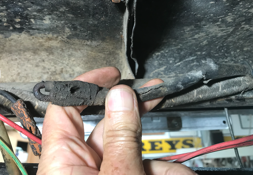
Many thanks for your detailed reply. The relay looks like it is of the period with rust and dirt befitting its possible 70+ years. Certainly the wiring is original and it is so old that I am guessing at the colours but I will go in with some cleaners today and investigate more thoroughly. The mounting set screws and nuts are imperial. Same paint on the bar as is on the car, but that could have been a respray but must have been prior to when the second owner bought the car in 1968. Meanwhile here are some photos.
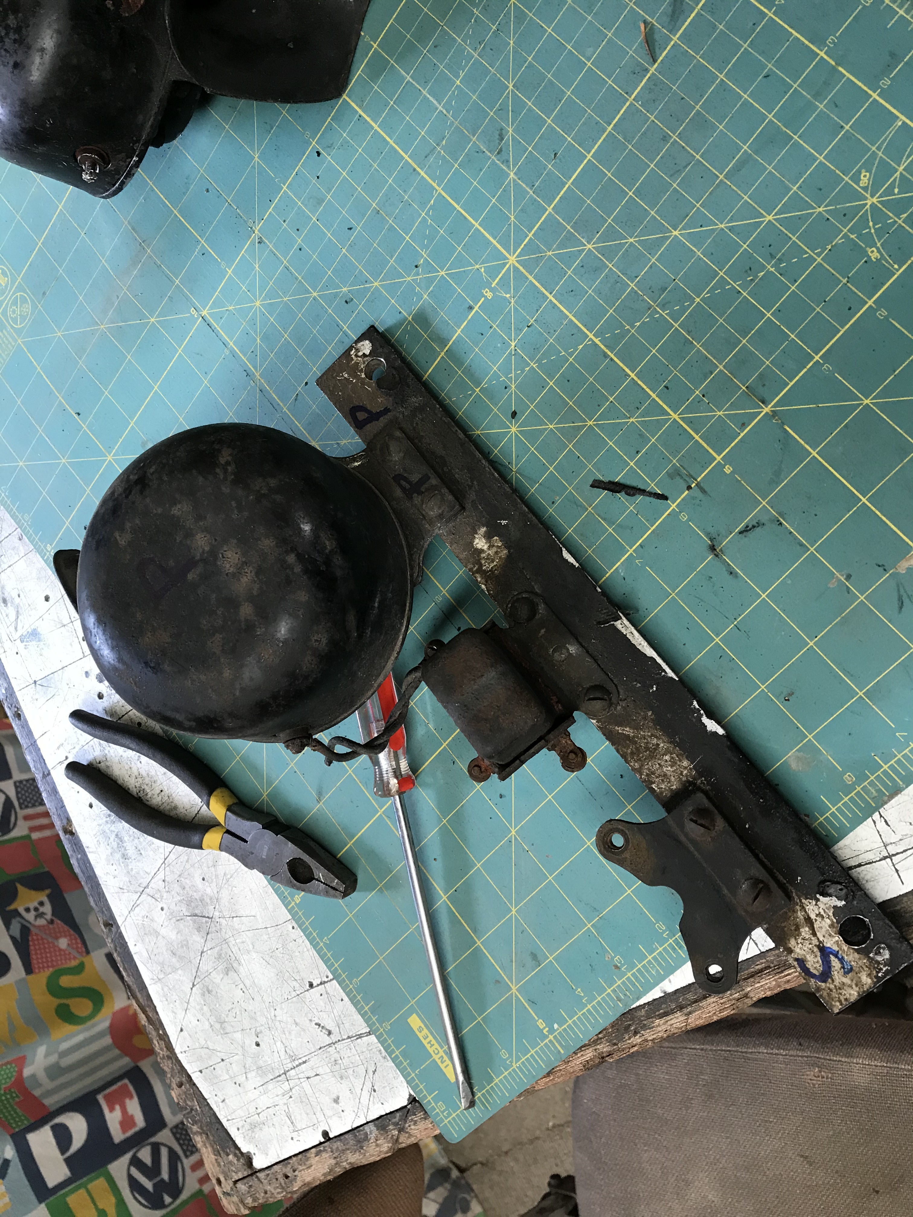
The bar with horns and relay released and swung down from the retaining bolts above. Horns face rearwards when mounted. The modern red and green/yellow wires and the yellow terminal on the horn are my work when fitting indicators in 2003.

Close up of the relay.

View of horn assembly from the rear looking forward. Note terminated wires from loom above.

Close up of relay.


I will return to the dilemma with my multimeter in due course and hopefully give some answers soon. However I am doing this without my friendly mechanic mate in support as we are complying with the coronavirus isolation advice . Apart from that electrical matters tend to mix up my ageing brain cells!
Good wishes and good health to you all out there.
Darryl
It appears that my car was modified to accept new horns of an Australian made variety (RVB) at some time in the past and the fitment included placing a relay in the circuit to avoid the full horn current coming through the steering column and horn button.

The cause of the failure was simply a dirty fuse contact at the voltage regulator. Did not show up with the test lamp but failed under full current! It just goes to show that you should listen to your mates and do the clean up job thoroughly!

Thank you to the responders. Stay healthy out there! Regards
Darryl
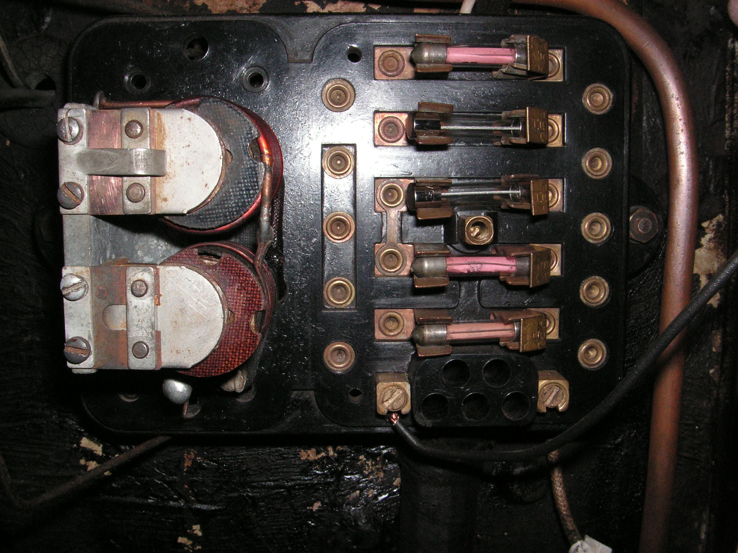
That’s very interesting. I had never heard of RVB horns, but they look a lot like Lucas. I notice you also have the same fuse block and voltage regulator as Mark V and XK120.
I had to take my '38 voltage regulator out and give it a thorough cleaning in pool cleaner before many of my circuits would work.