Dear All.
Help required please.
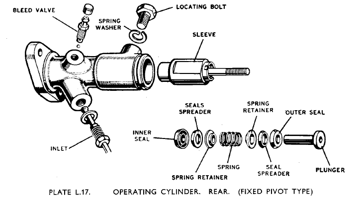
The rear braking system on our MK V Drop-head Coupe’ as pictured.
On dismantling, apart from all the other issues we have had to deal with - Item 65 (PN H.2515)
on the drawing was missing. If known would you please advise what this part looks like, better still if there is a sample available, also how it is fitted to the piston/cable locking nut.
All responses are very much appreciated.
Item 65 is called Pin and Spring Assembly, locking Cable End Screw. It must lock the end of the hand brake cable onto the threaded shaft in the wheel cylinder.
Unfortunately I have the later sliding pivot system so do not have the same hand brake cable.
This is from the Service Manual
I think all DHC’s at least those exported to USA had the sliding pivot type.
Is the OP’s (David’s) car in Australia or somehting and is it an early RHD car? I have never seen the early setup and associated parts, only the sliding pivot style.
Hi Rob and Pekka, thank you for your replies, very much appreciated.
Rob - the drawing you added is different to the actual set-up which is as is in the parts list, I will post some actual photo’s tomorrow.
Pekka - We are in Australia, the car is RHD, I will re-check the chassis number (on the Chassis) as the parts list advise this braking system was only fitted to a very few DHC’s.
Regards
David
Hi Jon
Thank you for the kind offer, please don’t go to any trouble.
The photo you have is what I have also and to reveal what I’m looking for you would have to remove the black cover in the photo which involves quite a bit of work, slackening the cable etc.
I was hoping someone may have had a sample of the “peg and spring” and/or could describe how and where it fits.
Best Regards
David
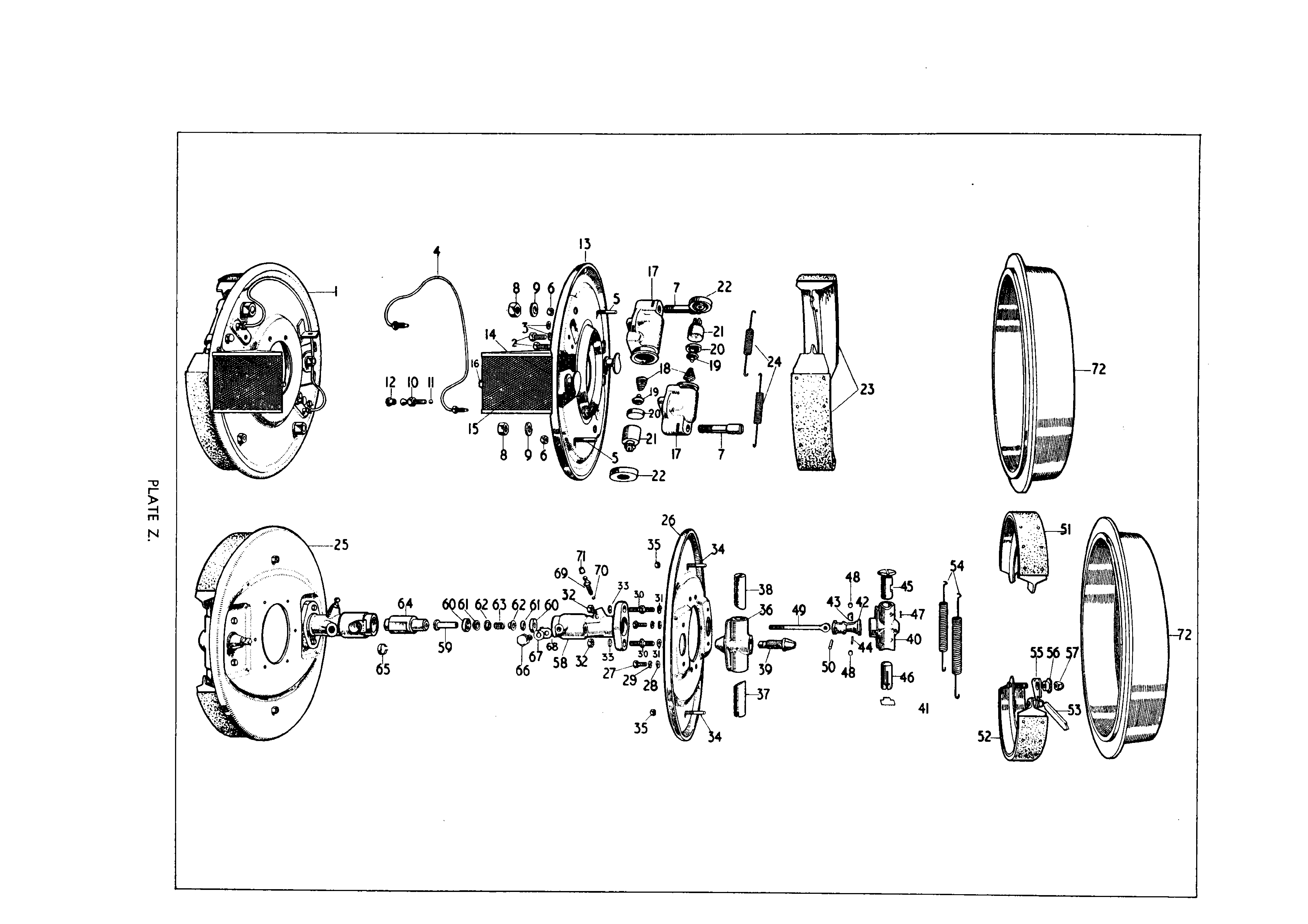
I think the page from the manual is misleading. Ignore the assembled rear plate on the left; piece 64 is orientated to insert in the RH rear plate. Threaded rod #49 goes through the centre of both the seals and threads into #64. 49 is pinned to 42 that is tapered. 64 is forced to the diff direction either by fluid entering between the two seals #60 or by the handbrake cable. 42 then acts on two roller bearings that force the wedges out that act upon the shoes… Either that or its all magnets
G’day David,
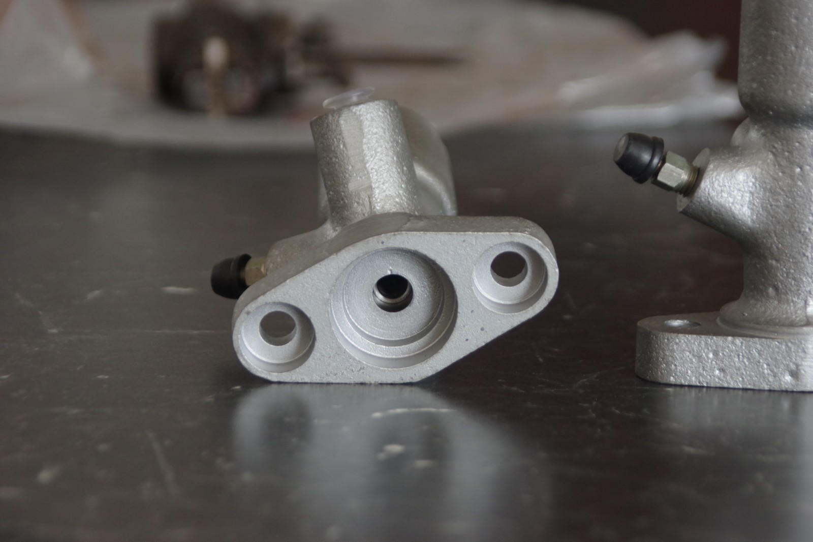
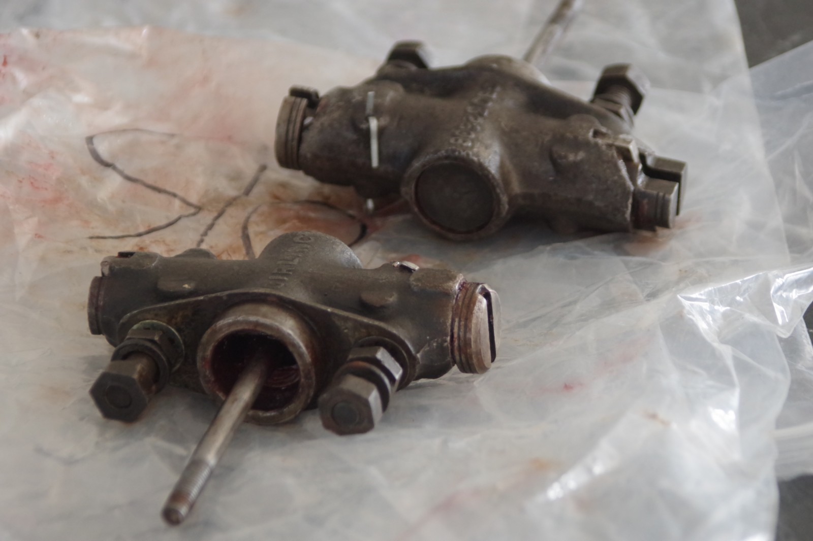
I have a 1949 saloon with the same brake system as yours. I had my rear brake cylinders refurbed by a South Australian company, so I can’t tell you how or if that locating pin is inserted or if it available as a stand alone purchase. I’ve attached some photos that might help. Nik C
Jon and Nik
Thank you for your replies, the explanation you give is as I see it and thank you both for the great photos.
Jon - interestingly, the photo you show of the LH side assembly shows the actuating plunger quite deep in the housing, as I understand it, normally with everything correctly fitted the plunger should be flush with the end of the housing, please let me know if this is not correct.
Nik - IMG3048 Great photo of the end of the sleeve, as you say, no sign of where the peg and spring are.
Best Regards
David
Jon’s picture shows a rubber boot over the cable end.
I’m curious and would like to see a picture of the fixed pivot cable end to understand how it is different from the later sliding pivot type.
It must thread or clip onto the 64 sleeve piston and pull it?
What is that threaded shaft I see on the sleeve in Plate L17?
I don’t see it on Plate Z.
Somehow it must pull the 49 threaded shaft on the cone.
Hi all,
Rob - from memory I think the boot is metallic.
The threaded shaft is what the handbrake cable is attached to. It threads into #64, or rather 64 is threaded onto the shaft. 64 has a slot down the side and a locking bolt 66 is inserted into the housing to prevent 64 from unthreading over time, whilst still allowing.64 to travel in the housing.
David, I think the photo is showing the other pivot point where the conical shoe adjuster is threaded into. That’s why it looks recessed.
Nik, do you think there may be parts at Mirboo from Colin to aid David?
G’day all,
Jon is correct in that the cap (boot) at the end of the cable is metal. It is held in place by a locating bolt, and I think from memory that bolt also locates the piston sleeve to stop it rotating. The locating pin that David initially asked about, from memory, just locates into a slot at the end of the inner handbrake cable and stops that inner cable from rotating inside the outer sleeve. If you zoom in on photo 3048 you can see the pin. I don’t know if Colin would have the parts needed in Mirboo North, I think from memory he had some a few years ago when I was after some, but I chose to have mine refurbished as the ones he had would also need refurbishing. Nik C
Dear All
Thank you all for your replies, I have taken the following photo with the layout of the system as it is laid out.
I notice the 1/8 (3mm) hole in the sleeve could correspond to the screwdriver slot in the cable nut when assembled, perhaps the peg/spring is fitted here. The chassis number on the chassis rail at the front LH suspension, best I can make out is 640200, the car is on the hoist at present to not able verify from the ID Plate, that will follow.
I don’t quite understand that threaded sleeve with slot on the end of your cable. What does that thread into?
Obviously something has to grab onto that little hex end fitting crimped onto the flex cable.
I have one Girling catalogue which lists Mark V.
Apparently no other car or truck used that particular wheel cylinder.
There are two pictures, neither of which seems to be exactly the same.
I suspect the catalogue printer made a mistake, failed to print picture letter i and printed picture letter j twice.
These are called External Transverse Wheel Cylinders.
Dear Rob
Thank you for your reply.
My guess is as the MK V was a “stop gap” model waiting for the MK VII and XK120, this was trying to adapt the MK IV rod pull system (that worked well) to Hydraulics.
Your question re the screwed nut with the slot, the screwed nut is screwed into the sleeve with the flat on it, (NikC photo3048 above) the spring clip and peg (that I am looking for) then is fitted, the peg going through the 1/8" hole pictured and engages in the slot in the screwed nut, to prevent the nut from unscrewing.
The hexagon on the cable is simply the fitting crimped on to the cable by the company that refurbished the cable.
A friend (toolmaker) is suggesting to make a spring clip with a peg, it would be great if I had a sample to copy.
Best Regards
David
I should have explained that Girling made several other models of this External Transverse Wheel Cylinder, in much larger sizes, for various trucks, cranes and other equipment including Albion, Commer, Dennis, ERF, Guy, Maudslay, Ransome & Rapier, Seddon, Taskers, Thorneycroft, and a delightfully named Yorkshire Patent Steam Wagon Sweeper. The Mark V seems to be the smallest vehicle to use a version of it.
I think I understand the part you are needing. If you don’t find the correct one, you could make something out of wire that would wrap around the 64 sleeve and have a tail that would tuck down into the hole, or even tuck in on both sides, both holes, perhaps make it out of a coil spring.
Dear All - an update, thank you to my friendly Toolmaker, please see the attached, the red outline is the spring with peg inserted through the hole in the sleeve, tried it with the cable end screw - works a treat.
Regards
David
Dear All
An update, firstly vehicle is chassis number 640290 RHD, Drop-head Coupe’, thank you to Roger Payne for the following: built 3 May 1951, dispatched to Dublin, then to USA, then to Queensland Australia, now in Sydney.
Brake system as fitted, Front - sliding pivot type, Rear - fixed pivot type.
Finally the brakes, front and back, are back together, drums trued up, shoes relined, all new seals in master and slave cylinders, new ball bearings to bleeders.
When bleeding the workshop manual states" slacken off all shoe adjusters to zero on all brakes THIS IS IMPORTANT."
Question is - Why is this important ?
Any replies are much appreciated.
Regards
David