I am replacing the brake pipes on my 1966 LHD MK2, and was wondering if there is a picture or diagram somewhere of where the pipes should be routed and fixed when they cross the front of the car. This is the pipe from the master cylinder to the servo and the LH front pipe to the 4 way splitter thingy?
Thanks for the picture, it will help me get that bit right. Wish my engine was out and I had that kind of access!
I was really looking for how they cross the front of the car as they seem very vulnerable where the old pipes were fixed?
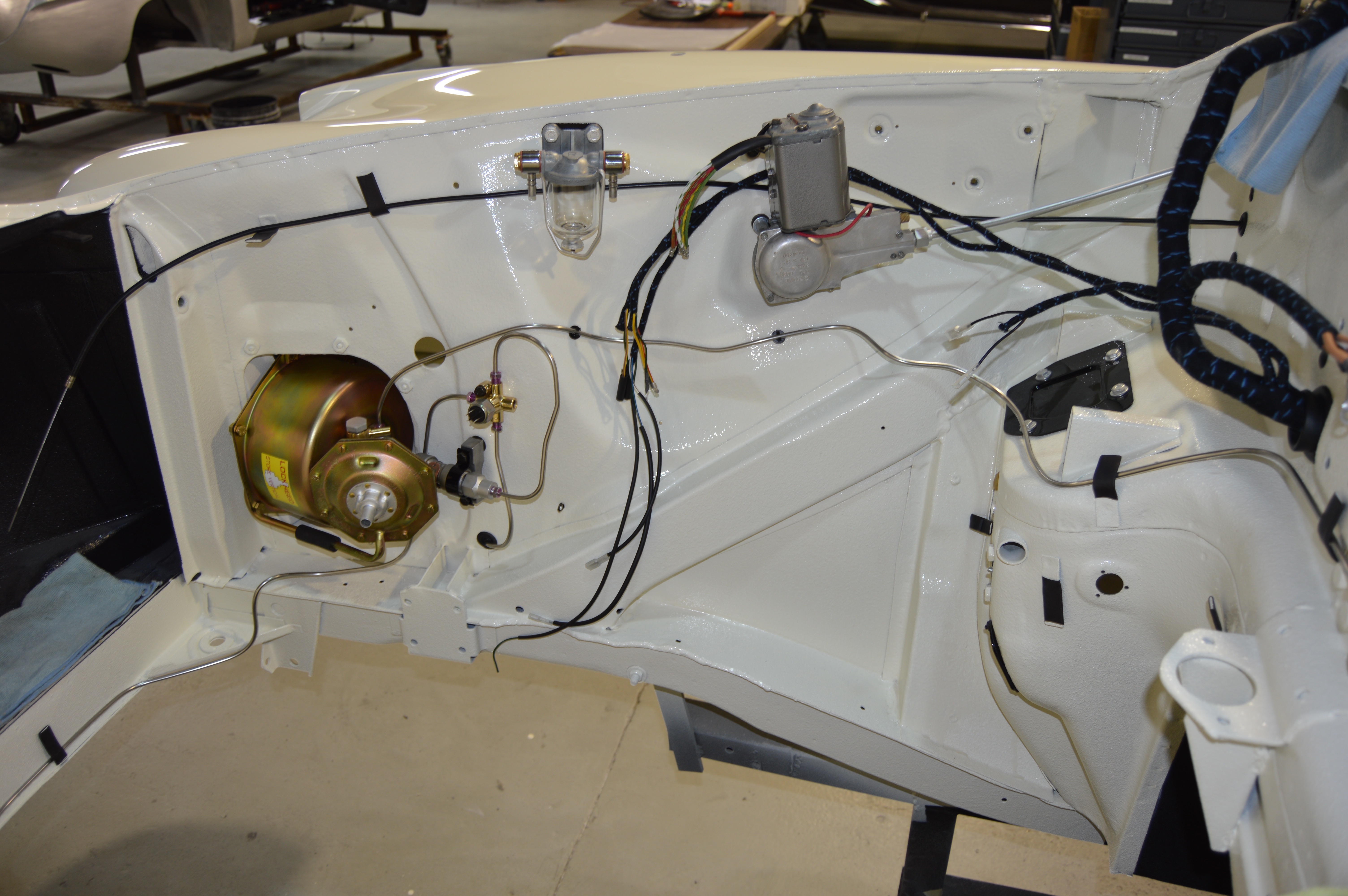
This is the best photo that I have that shows how the brake pipe crosses beneath the radiator. The routing on the left hand side of the car mirrors what you see on the right hand side. Note that the I had not yet installed the clip that presses into the horizontal surface of the front frame rail (beneath the brake servo breather diaphragm) when I took this photo. There is supposed to be one clip on the right rail and one on left rail to positively locate the brake line.
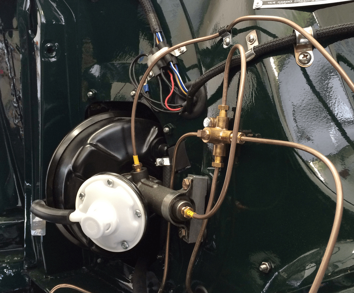
A detail of the front right corner brake line going from the 4-way Tee across the front of the chassis (it’s almost the mirror image on the left side) :
I covered my metal clips in bright green heat shrink BTW and you can see one clip at the bottom far left. I also covered the front line with rubber tubing for protection, but this is not the way it was done at the factory!
David’s photo above is an excellent overview of the entire right side.
Instead of the OEM hydraulic switch, we installed an electric brake switch positioned by the brake pedal (see question by JagMan above) as shown below:
Thanks for your pictures, in the middle of this project right now. Old servo line to master went around front under rad, new replacement line obviously goes around behind engine. Thanks so much.
Snowball