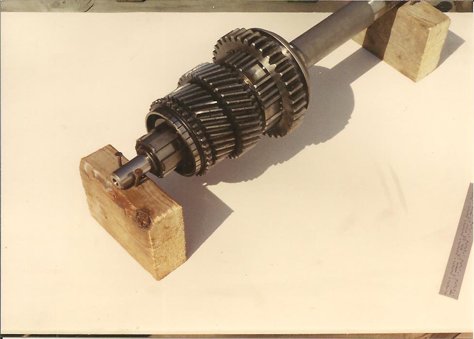
Hiya, this is an E-type shaved gear box (not the close ratio one) but I think it’s pretty similar to the XK boxes so I’m cross posting since there are undoubtedly more Moss experts here.
This box was rebuilt a couple years ago with new 2nd/3rd gears, new 3rd/4th synchro assembly (both inner and outer), new layshaft cluster gear and new needles. Since then 3rd speed has been unusable. It’s out now and I’m trying to get as much useful information as possible before I tear into it further tomorrow.
My suspicion is that the fellow who did the work either assembled the synchro parts in the wrong orientation, or he slid them onto the shaft in the wrong orientation. There is also the remote possibility that 3rd gear or the synchro sleeves are just bad parts.
This is how it’s behaving. Screen left is the front of the box and 4th gear, right is towards 3rd gear. Note how it behaves differently.
Am I correct in my understanding that as the fork pulls the synchro back towards the gear, the syncho should spin up, before it finally pulls the outer operating sleeve off of the detente on the inner synchro sleeve to engage with 3rd gear? This is what it does when I shove it forward toward 4th gear. But there is zero friction when it is slid back.
Are there any other tests or checks I should perform before tearing it down to find this or other problems? I haven’t noticed any issues with 1st, 2nd or 4th.
Going on my experience with pre-war and XK120 gearboxes:
My guess is that your 3rd/4th synchro parts are installed wrong.
Your synchro sleeve is moving when it shouldn’t, or not moving when it should.
There are two detents in the main shaft, offset certain different amounts, and the synchro sleeve has to be installed to match these detents. In other words there is one right way and eleven wrong ways.
That one looks remarkably similar to mine. I’m not sure what you mean by this part.
Is it moving somewhere it shouldn’t? The second part would make sense if I’m correct in my assumption about how it should operate. Is the synchro assembly meant to slip far enough to make contact with the cone on the gear? It seems like it’s bottoming out before ever reaching 3rd. I haven’t stuck a feeler gauge between the two parts but I suspect a pretty big one could fit.
Do you understand how the balls and plungers work? I was trying to puzzle this out from the manual and photos. Unlike the springs and balls that hold the inner and outer sleeves together, there doesn’t seem to be any spring pressure on those other parts. What causes them to engage with those slots in the main shaft?
Well one is down, but I can’t go through this 10 more times.
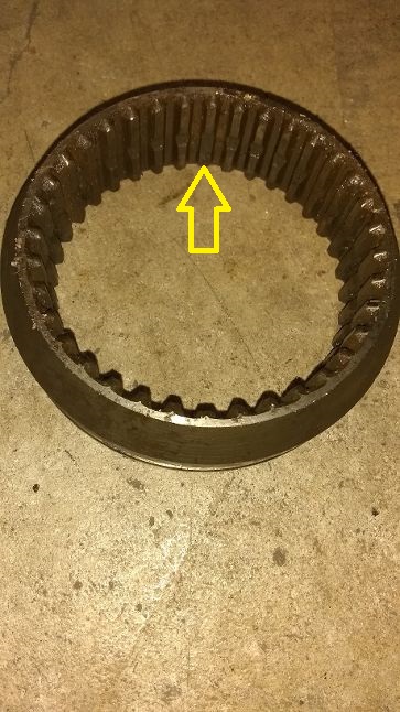
When you want to shift into 3rd or 4th, the operating sleeve moves the synchro sleeve, and each ball/plunger pair moves either into the notch or into the relieved tooth, preventing the synchro sleeve from moving in the wrong direction. The synchro sleeve rubs the synchro cone to synchronize their speeds. Then the operating sleeve moves over the little boat shaped teeth on the gear, and you are now in gear.
So I think either the synchro sleeve is installed on one of the five wrong ways on the main shaft, or it is on backwards and all six ways are wrong.
Or a ball/plunger is missing and allowing the synchro sleeve to move the wrong direction.
The manual tells how to put this together.
When you go to put this together, you can try it without the spring-loaded balls, and see that you have correct movement with just the ball/plunger pairs in place.
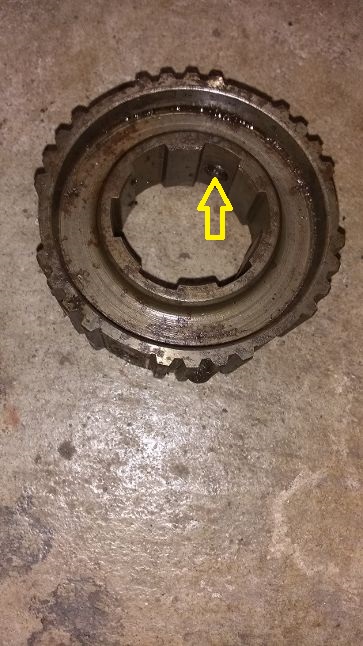
I got all apart and cleaned up for reassembly. The 3rd/4th inner sleeve was backwards
The fat boss hit the locking ring on the gear and couldn’t slip far enough. I didn’t notice that the plunger holes on the inside are staggered. I’ll measure and mark them tomorrow. IIRC the manual says the rearward facing relieved tooth should be inline with the forward sharft notch?
I tested my synchro sleeve release pressure and it’s about 5 pounds low on both of them. The dual one has no shims, and the 2nd gear one has pretty thin ones. The only way I knew they were in there is that two fell out while cleaning the part. The other 4 are still stuck inside and I need to figure out how to get them out so I can add thicker ones. Tomorrow is another day, but yay, progress!
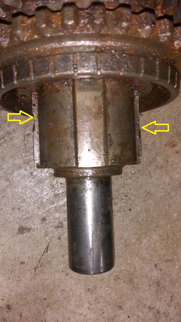
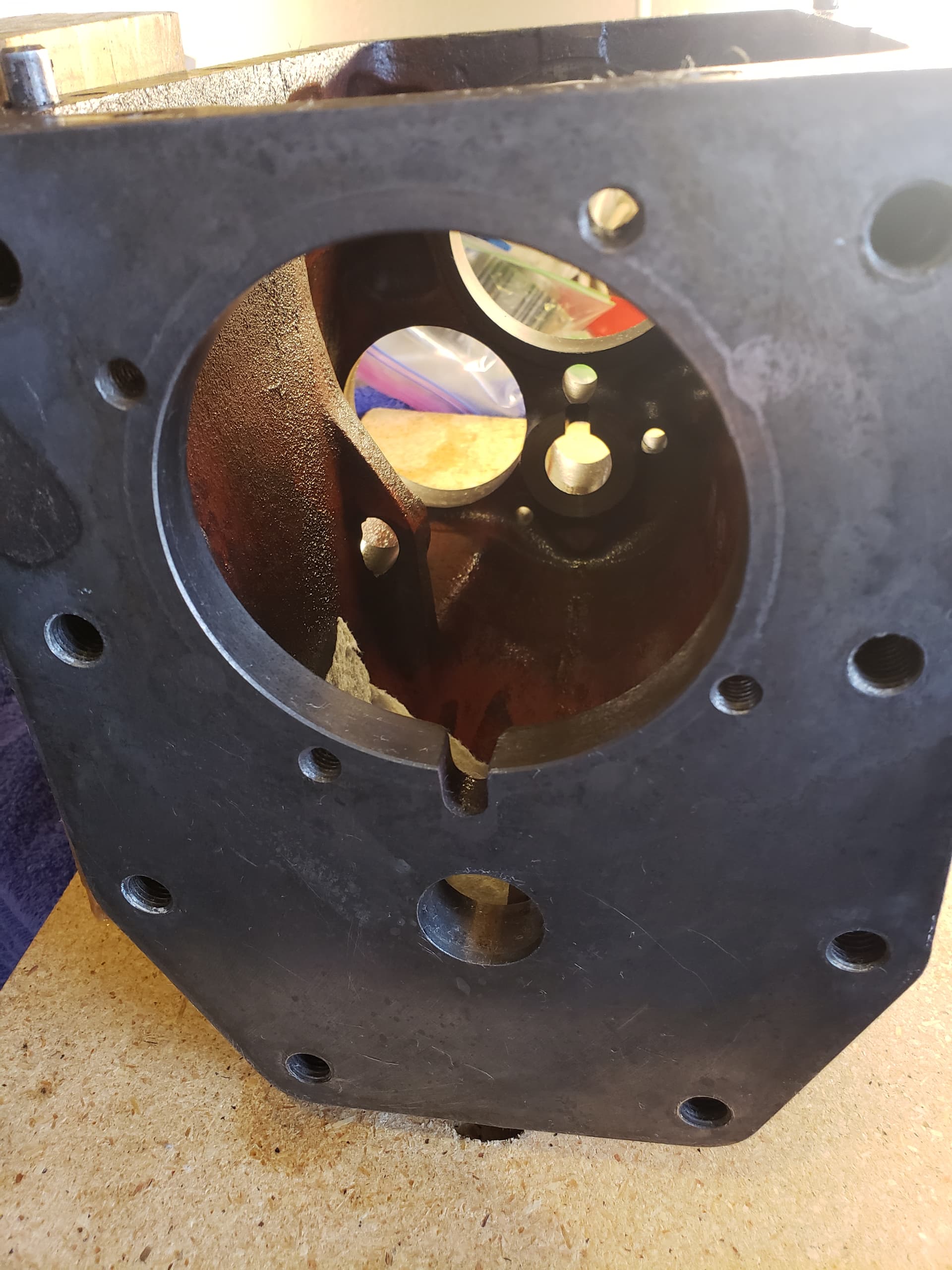
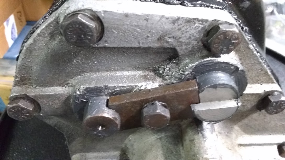
While cleaning up the case, I noticed these small holes for the first time. Not sure what they were used for, maybe another application or maybe they were used in the machining process. Any reason not to plug them to minimize the risk of leaks? Ideally I’d glue in bolt threads but not sure where I’d find Whitworth bolts this size. JB Weld maybe? There are several on the rear as well.
Since the countershaft doesn’t rotate, I assume no issues with applying some silicone on the end during assembly?
I think you’d be sorry if you plugged those 4 threaded holes.
But the 1" hole for the countershaft normally had a plug in it, so you can put sealant over that.
Ahh, so they were for a different application! Nothing goes in there on an E-type. The bellhousing alone retains the input shaft and bearing. The bell is retained by the 8 large holes around the perimeter.
Is third gear not usable at all or does it just grind going in? Does 4th engage? Is this testing only on the bench or have you driven the car with this gear box? I ask because I recently put in a JL box in my 140 and 3rd gear grinds but does go in. 4th works smoothly. I should say with the gearbox out of the car and on a workbench it appeared normal shifting in both 3rd and 4th.
The latter, I could go into 3rd only after waiting in neutral for the box to stop
Does 4th engage?
4th was actually fine. As seen in the video, when the synchro was pushed forward it engaged fine and synchronized with the gear.
Is this testing only on the bench or have you driven the car with this gear box?
It was in the car but not for very long because the new clutch broke. I was bench testing to try and get some useful data about the problem.
I ask because I recently put in a JL box in my 140 and 3rd gear grinds but does go in.
I don’t really have any knowledge of the full synchro boxes. If it’s basically the same design as the Moss but with the addition of bronze synchronizers, then it might be possible to test just as I did here, sliding the synchros into contact.
Art, it sounds like your synchro sleeve is not doing it’s job on 3rd, not sliding to the rear with the operating sleeve, missing a ball and plunger or on backwards perhaps?
I read my 1967 Chilton’s manual today and it says the forward relieved tooth inside the 3rd/4th operating sleeve corresponds with the forward of the two notches in the mainshaft. There are three lengths of plunger available, .490", .495" and .500" long. The longer nose inside the synchro sleeve goes forward. Slide the synchro sleeve back and it should drag on the 3rd gear synchro cone.
For confused XK120 owners with SH or JH boxes, we don’t have those notches and plungers in the 3/4 synchro.
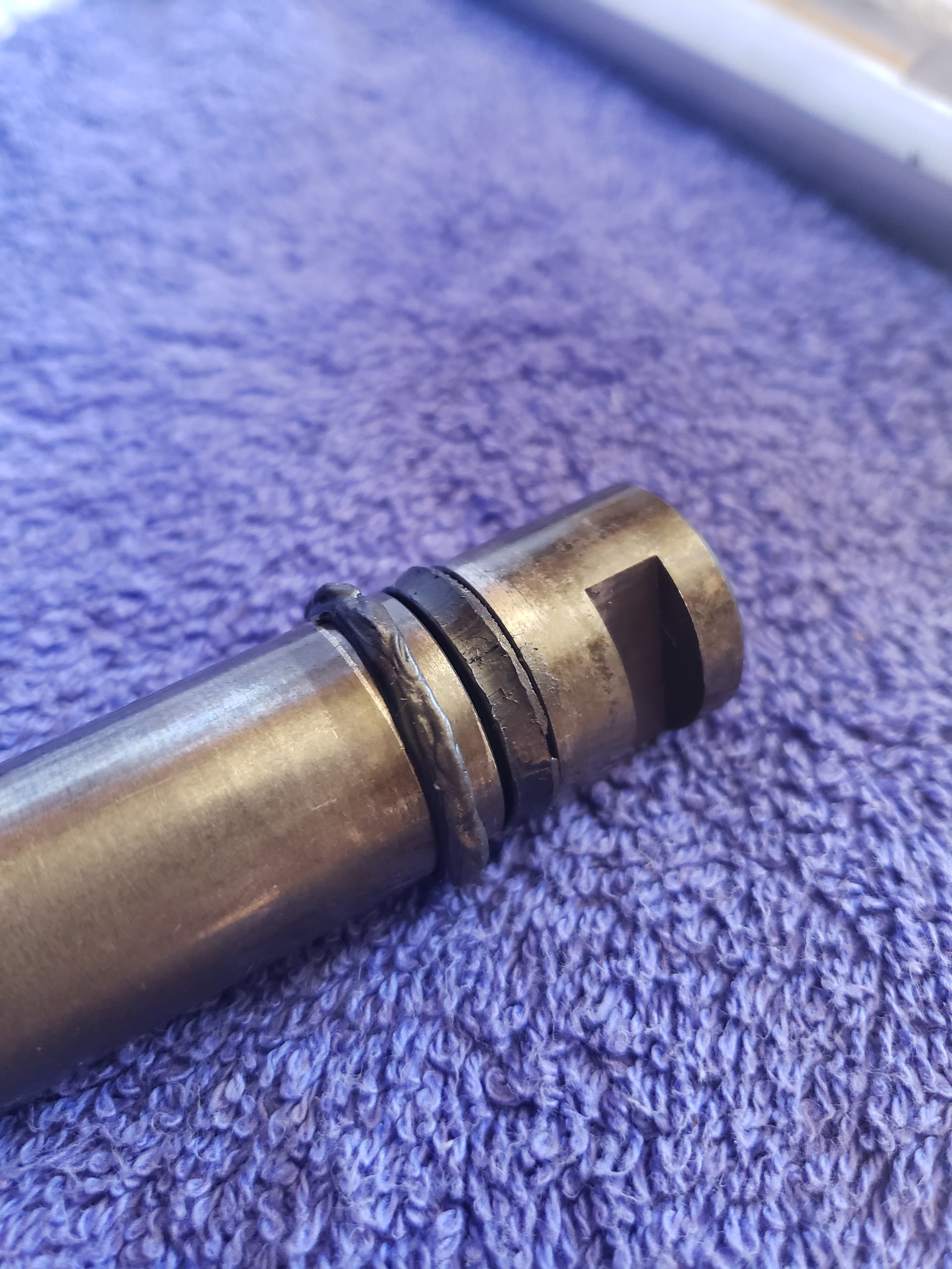
More weirdness. I disassembled the rear housing for cleaning last night and noticed this on the reverse spindle. There is what appears to be the original sealing ring is still in the rather large channel that fits into the hole in the housing. I can’t tell if it’s a flat profile or a very chubby and scrunched round profile. Then the last person that was in here installed the round profile one from the dealer in front of that and it was riding between the housing and reverse gear. It looks like it was getting eaten by the rotating gear and might have been devoured before too long. I assume the only seal that should be here is the one that’s hidden in the hole?
The problem is, that part from the dealer would definitely not make an adequate replacement for the original one. The channel is too wide and too deep for it to seal effectively. Do I have the wrong spindle or are they selling the wrong seal?
I have another niggling bit of minutia that doesn’t seem to be in the manual. I tried adding .006 shims to increase the spring pressure on one of my synchro assemblies and it was a bit too high whereas .003 was too low.
Can thicknesses be mixed to achieve the desired pressure? I’m thinking it’s probably bad, unless I was to alternate them thick/thin/thick thin. I would assume that in that case the pressure would remain even around the assembly, although it might cause the 3 balls that have thick shims to wear a small bit faster.
They are selling the wrong seal. Looks like it was sliced off at installation.
It should be a square cross-section seal.
I measure the shaft at .812" OD and the groove at .647" OD and width .175", so the o-ring ought to be size 208.
McMaster sells them for $9.29 in a pack of 50.
I wouldn’t get overly concerned about getting the shims for adjusting the spring pressure exactly right. If it feels right, close enough is good enough.