Oh, while we’re at it: Any idea which components are likely to fail? Is this a case where swapping out aging capacitors might help?
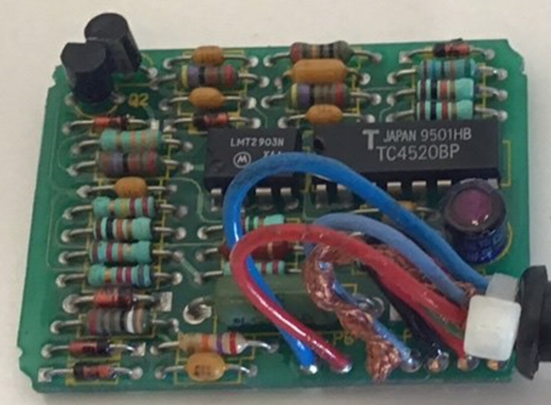
As far as I can tell, this thing does math (multiplication/division whatever), and shapes the output signal. That’s it. I couldn’t design this, but I might be far enough in electronics that maybe I could replicate it, and/or find substitute chips that would do the same functions + re-draw out the connections since it’s simple, and they should be obvious on the other side. The pick is just the interface w/o the black case around it.
AFAIK both the Trip Computer & the Speedo are looking for an 8000ppm (pulse per mile) …square wave (I think) pulse train (which is one of the typical speedo standards) since the feed off of the same wire in the older system. The 8000PPM thing is documented elsewhere on a page devoted to the SIII trip computer.
~Paul K.

I’d be right with you betting on the caps.
There’s a document showing how to rebuild the 45 second timer & all its components. It would seem easy to make one for this. I mean… breadboard… I’m expecting solder blobs running from one component to the other on the back of that thing… no etch/photo-resist layer at all…
~Paul K.

No, this is on Superblue, my '94 4.0 … Sorry, should have clarified that earlier … 
To clarify, the change from the transmission mounted transducer to the differential mounted speed sensor was at VIN 142xxx or something near that.
The change from Lucas to Marelli ignition was at 156xxx or something near that
Cheers
DD
1 Like
Anybody have any idea how many PPM the diff sensor produces?
An interesting conundrum. I have a multi-meter that has a frequency counting feature (also a real oscilloscope if necessary) but how would I induce the pulses? Jack the car up and somehow spin the rear wheels at a known speed?
Gee, I was kinda thinking someone could just count the teeth on the carrier – presuming someone has one accessible to count. One could count them by removing the pickup, making a mark on one tooth, and then turn the wheels and count teeth until the mark comes back up.
Then, of course, we need to do some math involving how many rotations the rear tires make per mile.
1 Like
15 inch tire, 30 inch diameter times pi yields 94.25 inch circumference. One revolution covers 94.25 inches.
5280 feet is 63360 inches.
About 667 revolutions to cover 1 mile ?
Sounds about right. Another way might have been to just look up the specs on the tire, as rotations per mile is one of a tire’s specs. It supposedly corrects for the amount of “squish” that occurs when the weight of the car is on the tire.
I have been trying to figure out the travel computer on my ‘88; and thought the speed interface was the culprit. I have not been able to locate the one I need (DAC4864) at a reasonable price.
My speedometer and speed control work perfectly, the travel computer does not record distance, so distance traveled and miles per gallon are zero- fuel consumption is accurate (since I replaced the IC in the fuel interface).
I fed a square wave of about 3.5v on the signal wire at the speed interface connector and the travel computer registers 1 mile distance at approx 8000 pulses per minute (133 hz).
Short story is that I think the module shapes the signal waveform, amplifies it, and possibly is a multiplier/divider, but only for the travel computer.
I have not wanted to cut mine open, it is pretty securely glued, without a spare for fear of losing the speedo and cruise. The one in your photo is the one I’m looking for…
I’m confused. Didn’t you just confirm it requires the same 8000 PPM signal as the speedo and cruise?
Are there separate outputs on this module for speedo, cruise and computer? Or is it one output, teed off to the separate destinations?
More on this sometime tomorrow possibly & sorry to Jean about the direction this his thread seems to have taken w/ side information irrelevant to him. But I digress. Having found new pics of the guts of 2 diff (of several) models of speedo interfaces, it seems they all use the same set of chips (the same two ICs already identified), presumably modifying the output by resistor/cap combinations. (The speedo and tacho interfaces can be modified to take V8 pulse train inputs this way as well… documented at a lump conversion site). The newer 94-96 interface board is much nicer.
Re what wires are used I present the 87-88 elec guide. AFAIK the trip computer, fuel interface, and speedo remained the same between the two years, while the method of getting that 8K/mile pulse train changed.
1987: Note the transducer gets power shared w/ the trip computer, and it’s output on the yellow wire is split back to the speedo and trip computer and CC. In these year we weren’t given pin numbering unfortunately.

Then in 1988 the diff VR sensor appeared and the signal was no longer a single split wire (at least external to the interface unit.) See the red oval. I highly suspect, however, that both wires output the exact same signal, split internally.
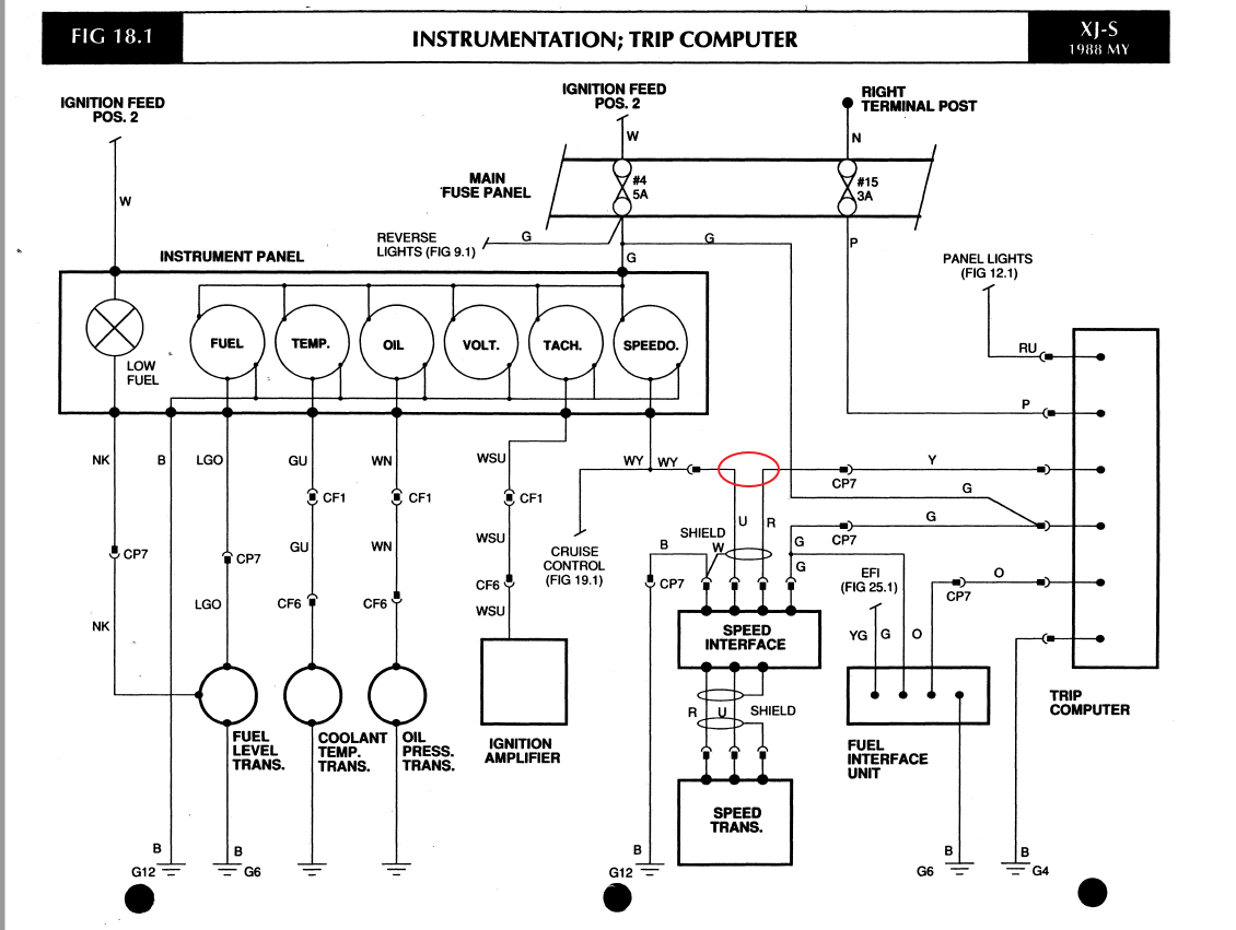
The wiring seems about the same in future years.
One of the good probably well known trip computer resource links:
~Paul K
1 Like
Separate outputs- one feeds the speedo and cruise, the other only the travel computer. I fed the 133hz signal only to the travel computer; didn’t try the speedo because it works. Don’t know amplitude or pulse rate of the speedo signal, but Paul indicates it is the same rate. It appears that the speedo may read the raw differential sensor signal when looking at the factory wiring diagram that I have(which is part of the owner packet and confirmed in Paul’s schematic).
It now appears you may be correct, as the output from the speed interface unit to the computer is separate from the output to the speedo and cruise. That would imply, though, that the failure is within a very specific couple of places within the speed interface unit. If, as Paul suggests, the output is the same and simply split off within the speed interface unit, the problem would almost have to be right there at the connector.
Hey, thinking a bit more about it: Forget trying to find a replacement speed interface unit and just splice the wire to the computer into the wire to the speedo and cruise. I’ll bet it starts working.
1 Like
I may look at that speedo/ speed control signal, along with the sensor signal, with an oscilloscope next time I have it off the ground. With Paul’s assertion that the processors are the same with the 2 interface modules that he has, I will order those parts in advance to rebuild the module that I have (I should have the capacitors and resistors on hand already).
In the meantime I may just jumper the signal as you suggest; I wonder why they would use the interface if the traveler could read the signal that the speedo uses.
1 Like
I did not count them when I had it apart, but from this pic one can infer that there are six surfaces that trigger the diff sensors. I think.
I’m not sure about everyone else, but I am having trouble with the English translation between Jean and the responders, so I am not really clear on what the problem symptoms are. Add to that the fact that this thread has been hijacked by other people posting their problems and being answered. I doubt I can help Jean with my limited knowledge, but I think it would help if everyone had a clear understanding of the symptoms Jean is seeing, and if other people start a new thread for their problem. Poor jean has been poorly served by all this off-topic discussion.
If I understand correctly, Jean’s starter turns the flywheel when the ignition key is turned to the start position, and the fuel pump is running, and the fuel injectors are firing, but the engine never fires up.
Beyond that I am not clear on the problem…
- Are the spark plugs/wires providing spark while the engine is being cranked with the starter?
- Has the distributor timing been checked?
- Does the engine seem to try to start, but dies as soon as the key is released from the starting
position? - Or does the engine just not ever fire at all (thus does not ever begin to start)?
1 Like
Six flats x 667 turns/mile = 4000 pulses per mile. Unless the pickup generates a pulse at both the step on and the step off of each flat, in which case it’ll total 8000 pulses per mile. And from the photo it appears the flats are the same width as the space between them, which would be necessary for the pulses to be evenly spaced.
Well, whattaya know?