I recently picked up a '71 S3 project, motor was removed for a 4 speed conversion. Most of the parts were included but not the clutch hard line from the master to the flex line, and the flex line to the slave. I can flare by own lines, I just need some reference pics of a LHD S3 to see how they’re supposed to look/terminate.
Also, I could use pics of the flex line bracketry both on the car and engine side (if the slave end attaches to the motor).
I intend to put the original motor back in but want to get the clutch lines sorted before that.
Thanks in advance!
Jake
Nothing, huh? Ok, I’ll look elsewhere
Jake
My 72 Series III is in pieces and I took a bazillion pictures as I tore it down.
I just spent the day (Saturday) at a major car show.
I am not sure what photos you are looking – don’t recognize CMC and CSC
Maybe some of these will come close


1 Like
Hi Craig,
Thanks, I’ve been using those acronyms for so long i figured they were common:
CMC - clutch master cylinder
CSC - clutch slave cylinder
If i understand the assmebly, there is a hard line from the master cylinder to a flexible hose, then another hard line from the flex hose to the slave cylinder. Im looking to see how the flex line is attached to the body or engine via bracketry, and the general shape of the hard line between the master and flex (where it runs in the engine bay). If its the same as a 4.2L, thats fine, i found pictures of that setup. Since the S3 slave mounts to the gearbox, its going to be different than the 4.2L. I havent seen any pictures online of the lower hard line.
Let me prowl around my hobby shop/photo archive and see if I can locate some more useful items
Like maybe this


1 Like
Hi Craig,
Thanks for continuing to look for pics. It seems as though the lower thread on the flex hose should go through some bracket or something attached to the engine or gearbox; there appears to be a jam nut and star washer in your pictures. That’s the last piece to the puzzle, i did find a picture with enough of the clutch upper line to maybe create one.
Thanks again
Jake
I think I have pieced together the final story line with a series of photos
The rubber/hard line from the slave cylinder on the transmission is attached to a small L bracket on the right (passenger)-center of the firewall (Mine got snagged by the engine during withdrawal; hence straightened)

Then this hardline (see line on far right of photo) is threaded onto it, flows across bottom of firewall to pedal box (on US model Jag). The fitting on the “hump” end of the line threads into the line from the slave cylinder (next set of photos shows that).

This hardline is captured in this photo (third/fourth from top) but in 2 halves (left and right) but provides a bit closer look


Here are a series of photos from the Interweb showing the line in place - nearly the same perspective but each is a little different (details in captions)


Even though this photo is of an automatic, the two threaded holes for the L bracket are evident (at least 1 of the 2 holes are) just behind the chole cables

Et fini - the line in place with nothing blocking the view (actually I found this in my archives after finding the above 3 photos with the engine in situ) – the money shot
I’m on a roll – what else ya got:
PS - interesting call sign; your family ranchers?
1 Like
Hi Craig,
First off, thank you so much for these pictures. To me, they’re worth more than myriad words!
I should be able to create new lines, brackets, etc to make this work.
I did manage to find a single picture online of the lower flex line bracket. Seems to be under the head of one of the bellhousing bolts on the RH side.
As far as the forum handle goes, I lived a few years in Italy as a church missionary, learned to speak, read and write in Italian. ‘Barbed wire’ seems to fit me, somewhat. No ranching in my recent heritage, my dad was the proprietor of a British car garage and parts business. That’s how I developed Stockholm Syndrome for these cars that we all seem to have in various degrees.
Don’t know how fussy you are vis-a-vis originality / appearances
BUT
since my Jag is still in pieces, it would be simple for me to take a few happy-snaps of the long tube that runs along the lip of the firewall.
I could lay a tape measure along the tube to give you some basic measurements. Let me know.
AND
there is another hard line (that joins the line to the gearbox with a section of rubber hose ) that runs from the top of the gear box, is secured to a bolt on the bell housing, and ends just at the bottom of the firewall.
See item #35 on below
Also needs the small black plastic cap, attaching bracket.
This line is a vent/breather line.
For $37, it (#35) is available from SNG Barratt. NAYYY.
xkedata.com is really nothing but pictures. The photo albums section in the “old site” section of this website likewise. You can also search this site and may find other members have included photos in their questions or replies.
kind regards
Marek
1 Like
Hi Craig,
This car is going to be the epitome of ‘driver condition’. Any pictures or measurements of that upper line would be really helpful. If you can fish a string down it, that’d give a good length approximation. Tape measure also works.
I do have the vent tube, it was on the XJ transmission that came with the car. I swapped the shift cover for an XKE one and moved that tube over. I do need to get the breather, though.
Slowly moving forward. Thanks for all the help.
BTW, if anyone has a clutch pedal, I’m on the lookout. Thanks!
Jake
The captions have the details:

.
.
.
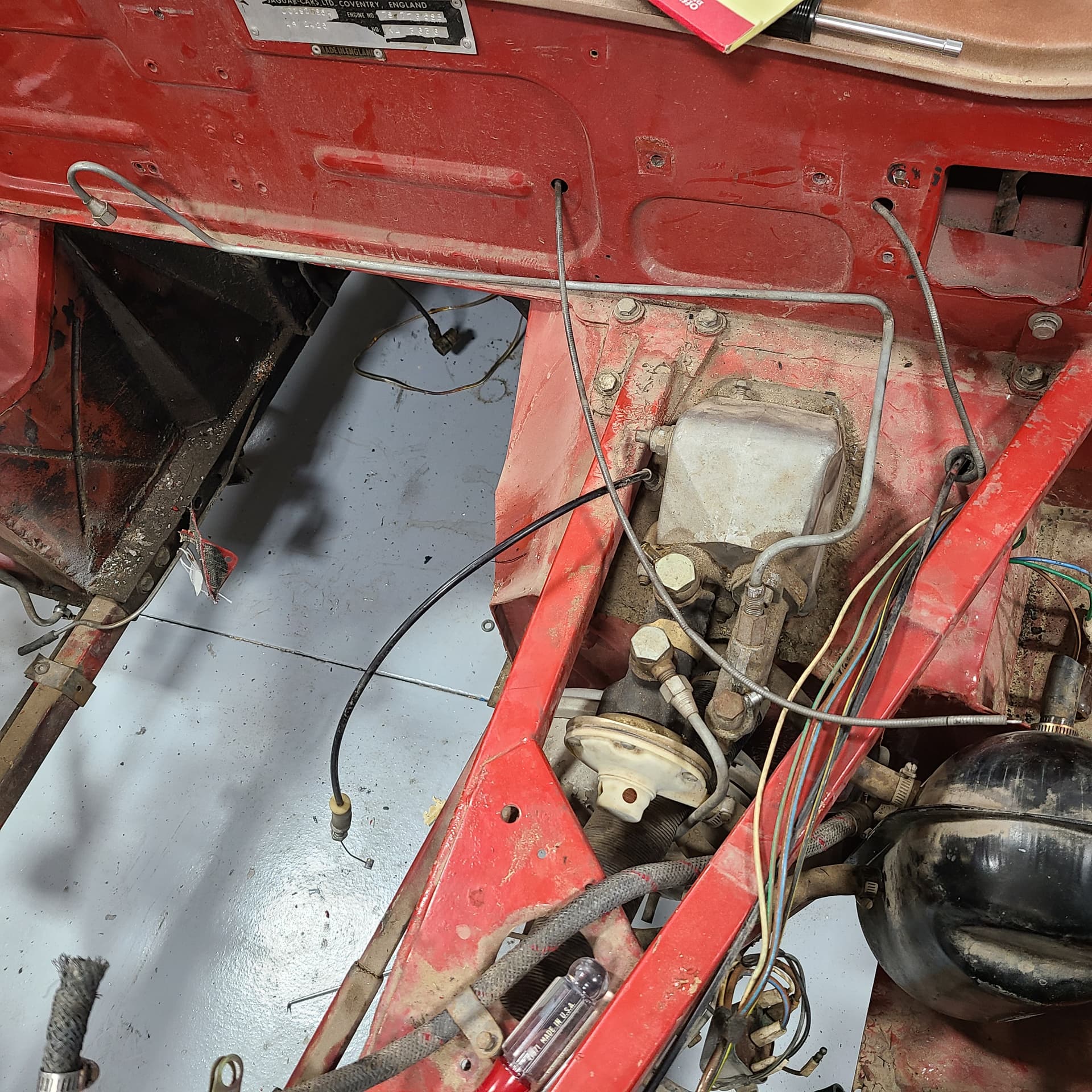
It isn’t as clear as I thought it’d be - this is a close up of the tube after the 180° bend on the firewall and starts the measured length of the tube moving outboard toward the pedal box. \/

Confusing placement of this photo - this shows the overall length of the tube \/

\/ I typo’ed the hell outta this caption - The sweeping 90° turn that turns away from the firewall toward the CMC starts at 20-5/8" as measured from the final bend of the tube (see second photo above).
I suspect the bend you build into your tube will best navigate around the pedal box and any other obstacle(s). \/

\/ I didn’t notice until now that the 180° bend on my tube is cocky-wobbled. I may/may not try to straighten the legs of the180°. BUT - I suspect the angle you see is driven by the distance between the various fittings/bends.\/


\/ This final bend is complex involving 2x near 90° bends – again, the bend you incorporate into your tube will likely best fit the fitting on the CMC and nearby obstacles. \/

NOTE - there is 1x P-clip that holds the tube in place. It is secured at both ends with the fittings, but the P-clip secures the tube to the firewall at mid-length, just inboard of the driver’s side frame bolts to the firewall

This is fantastic, Craig.
Thank you for your time to set this up with measurements visible.
I picked up a length of straight tube and will try it out soon. Can you confirm the tube diameter? Im assuming 1/4".
Your assumption is correct – 0.2495" - 0.2505"