Pre-HE Pertronix Installation with trigger board

Hi All,

I’m Zack and I’ve been lurking around here for a bit now mostly finding myself at the site over and over again via google searches as I work through some issues on a newly had 1977 XJ-S (pre H.E.) in decent condition that’d been sitting in a garage since 1995. I wanted to share the following as I suspect it may be very helpful to someone down the road as I couldn’t find any information on the topic.

This is specifically relating to the use of a aftermarket ignition system on a Pre-HE engine that uses a fuel injection pickup in the distributor.

Here we go:
After spending some serious time fiddling with the OPUS system in the car and subsequently rebuilding the resistor pack, I found the amplifier just wasn’t doing it anymore. The transistor was toasted.

Not looking to repair the OPUS, not loving the cost of the new system from SNG and afraid of future availability of the crane system, I found the Pertronix ignitor II system which was particularly appealing as it’s just so simple. The problem here is that Pertronix says on their website that it’s not for cars with the fuel injection trigger board in the distributor such as mine.

Well, I couldn’t get a straight answer from anywhere on WHY this was the case, I called Pertronix and they didn’t seem to know and searched the web to no avail.

So, I ordered the Ignitor II, (9LU-1122A) and a .6 Ohm coil to match.

Well, it finally came in yesterday and I’m happy to report that with some timing adjustments, the car is now running again.

Why and how:
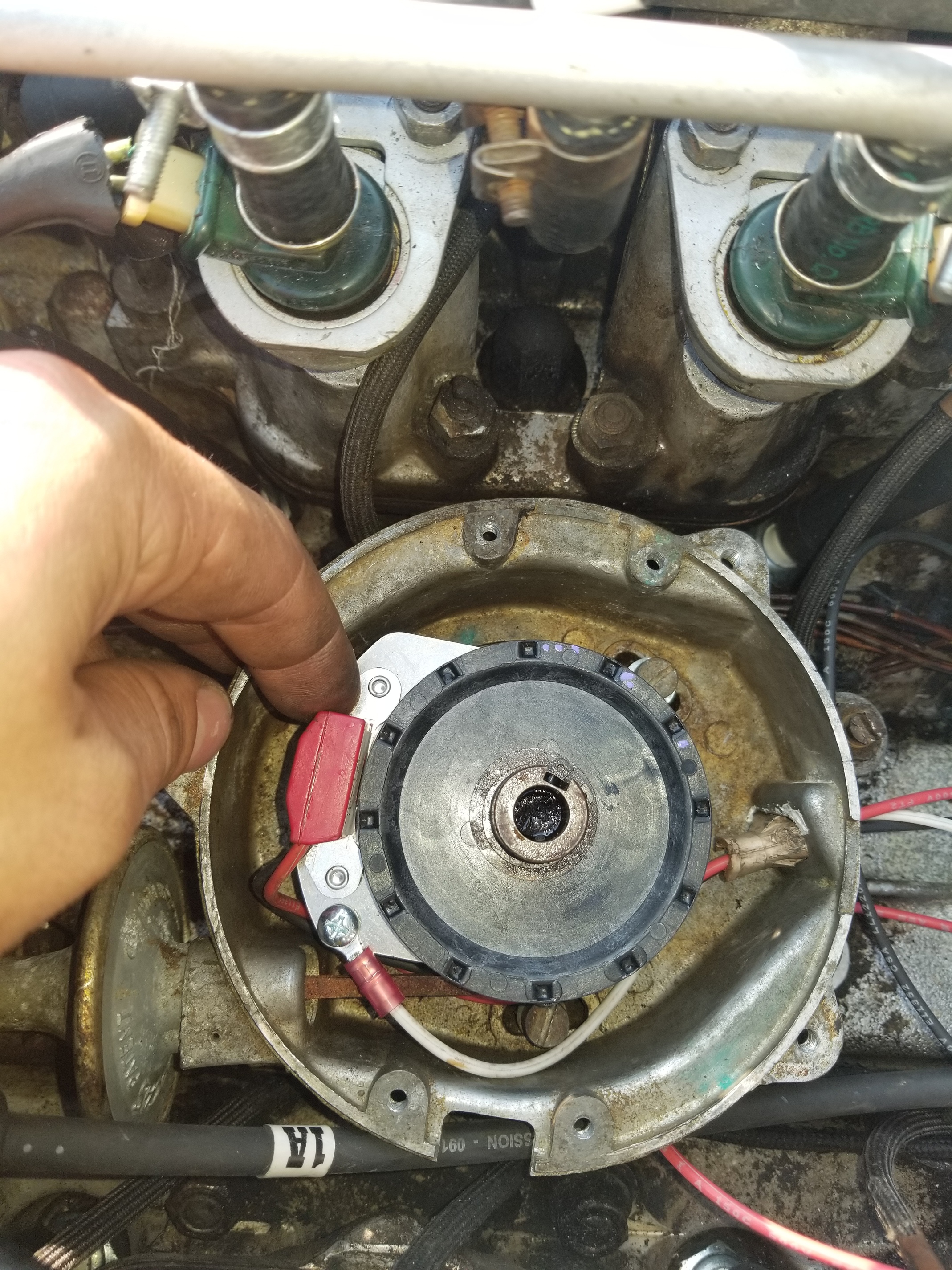
It turns out that Pertronix demands the position sensor be mounted OVER the vacuum module arm; This just doesn’t do as it will interfere with the fuel injection trigger board. So, I positioned the sensor a little bit different than instructed and much closer to the factory position (but not quite the same).

Then, I made a little eyeball timing adjustment to accommodate.

Next, we’ve the reluctor wheel which is calibrated to THEIR position for the pickup. NOT where I’ve mounted the pickup. Consequently, the points on this wheel are not in the same position as the factory Lucas reluctor relative to the keyway on the shaft.

Another eyeball timing adjustment made to compensate.

Finally, It all came back together and after a little throttle coaxing, the XJ-S came back to life.

The Ugly:
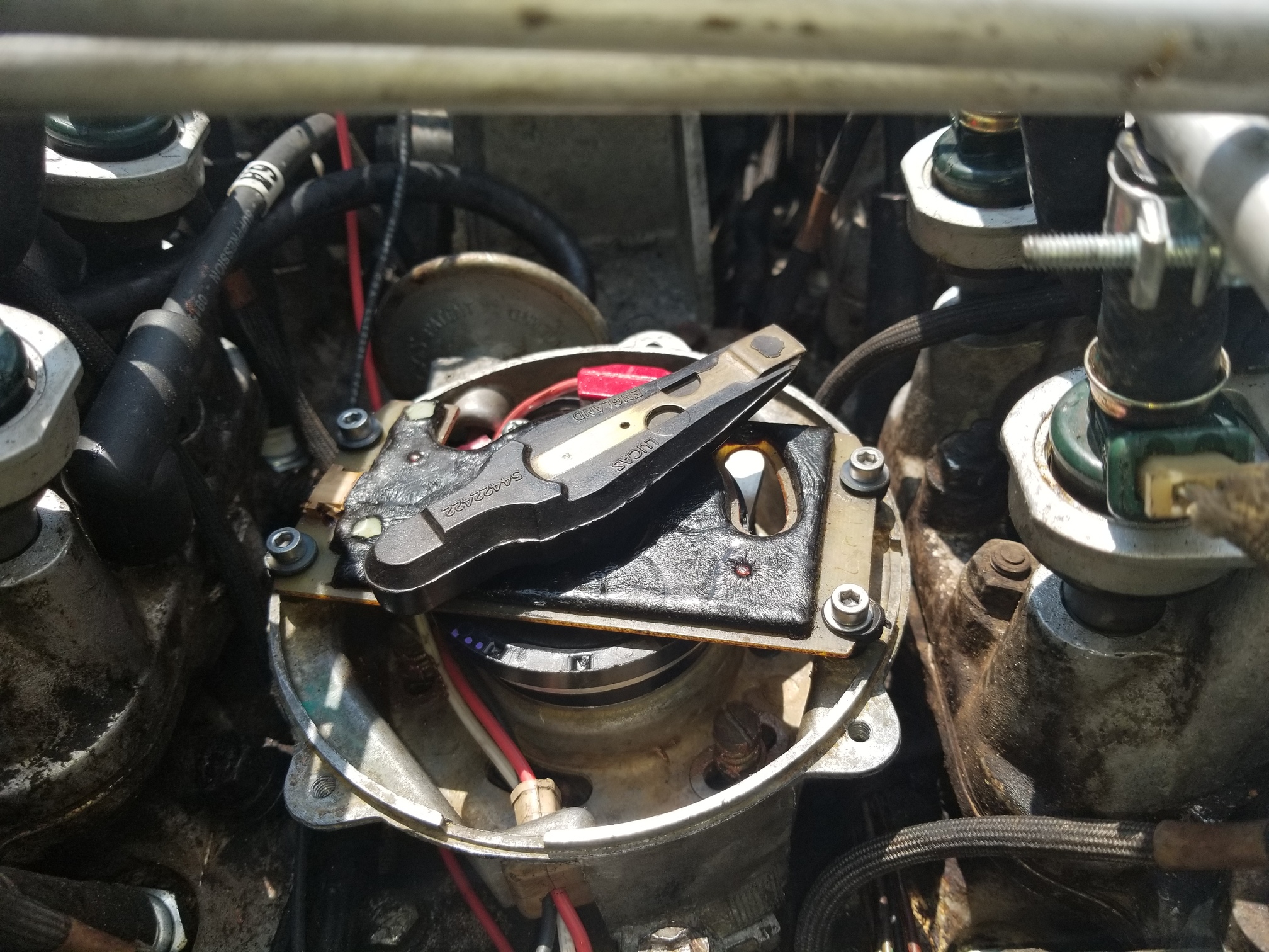
The Pertronix system uses a pickup mounted on a metal plate that’s mounted on a plastic bracket that’s spring loaded onto the distributor. This plastic bracket is NOT snug like the factory pickup bracket. there’s about 3/32" of play to either side. Fortunately, even if it moves around, it still clears the reluctor. The pertronix coil is larger than the factory coil, a new mounting bracket must be had.

Conclusion:
I’ve still some work to do in the way of timing adjustments before I feel comfortable giving a definitive “this can work” answer but I’m happy to say, there may be a solution for a toasted OPUS that’s less than $700.00 and doesn’t involve searching high and low for dead stock crane systems.
I haven’t even started tinkering with the tachometer yet but I can’t see why this won’t work with a resistor in the path.

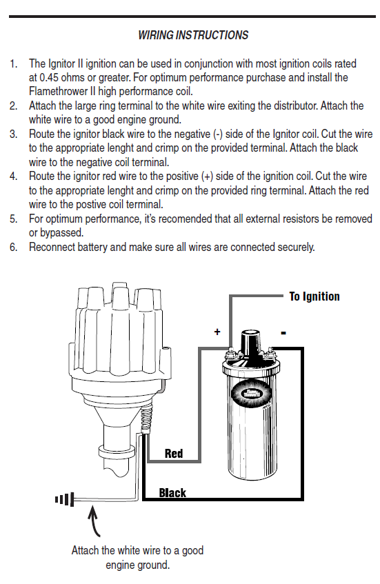
Here’s a picture of the new system. The white wire grounds to the engine, the black and red to the coil. That’s it. No amplifier.

3 Likes

Why did you choose this model over the 9LU-1121A?

Hi,

I ended up with the 9LU-1122A as it’s what’s listed from Pertronix as correct for the distributor I have (36DE12)https://pertronix.com/electronic-ignition-conversions?year=1977&make=Jaguar&model=XJ12,%20XJS,%20E-Type#auto

It seems as though the 9LU-1121A is made for a later model, H.E. distributor- It says 82’-84’ in the applications at your link. I’m not sure what the H.E. distributors look like in that date range, but the picture of the unit shows a different aluminum mounting plate.

On a slightly different note:
I had some concerns about interference, magnetically speaking between the units as the trigger wheel changed size but I’m not seeing anything to tell me that’s the case yet. Shielding will be in order if it comes up.

That makes sense. Looking at the photos of the parts, though, it appears that the 9LU-1121A is designed to mount onto the vacuum advance plate, while the 9LU-1122A is designed to replace the vacuum advance plate. In hindsight, do you think maybe the 9LU-1121A might have worked better for what you were doing? Presumably the disk and the pickup are the same, it’s only the mounting hardware that’s different.

BTW, I think I understand why you couldn’t install as instructed. However, the mounting plate attaches to the plastic support with 3 screws, so the first thing I’d try would be to rotate the assembly 120 degrees and screw it down at a different orientation. Being a V12, that should have made no difference to the timing.

I see what you’re getting at with the “1121A” model.

The Disk and pickup are certainly the same for all V 12. The pickup is probably the same for all the Ignitor II systems.

Problem is, I can’t see how it would mount on the factory vacuum module (A.K.A. pickup arm) It’s not so much a plate on here as it is a molded piece of plastic. - Here’s a picture of the original scheme sans reluctor:

You wouldn’t happen to have a picture of the vacuum advance plate from a 1982-84, would you? that may help us understand the difference.

Regarding the mounting position-
You’re completely correct. I never ran the math but now that you mention it, the numbers work; Rotating 120 degrees would work on a 12 Cylinder as the “points” are all 30 degrees separated- The reluctor doesn’t care what cylinder it’s firing.

360 Degrees / 12 Cylinders= 30 Degrees apart.
120 degrees of rotation / 30 degrees = 4 positions of movement.
End result- No change, assuming the timing is evenly spaced, and I can’t see why it wouldn’t be.

I should probably start there when adjusting timing back home.

For posterity- A picture of the factory wheel and the Pertronix wheel, both on the shaft showing orienting position- not terribly useful as the pick-up arm is different, but interesting.
The purple marks are from me making notes.

The 1122A wouldn’t, but the 1121A might. Take a look at the parts in that kit.

Looked at the 1121 again and I don’t think it’s the way to go with the OPUS pickup and Reluctor that was used in my vehicle (see above for pictures).

Perhaps some later distributors are different and it would work in that application.

I do now have the vehicle reliably starting and running. To get it there I needed to static time the vehicle with the old pickup and reluctor using instructions on Mr. Sowell’s site here-

http://www.efsowell.us/ed/jag/engine/distributor/overhaul/DistributorOverhaul.htm
Once I had it set, I took off the old parts and replaced with new again.

In the end-
I’m comfortable confirming that the 9LU-1122A kit and matches coil works on my 1977 XJ-S pre HE with a fuel injection trigger board in the distributor by mounting the pickup 120 degrees from the specified mounting position (closest to the original pickup position)

I hope someone is saved their OPUS frustration.

1 Like

Read with interest your post and Kirbert’s comments. It appear the Pertronix may be a viable replacement of the Opus pick up and amp for my 1978 xjs prehe. About to renovate the distributor lubricate advance weights etc as per Kirbert’s recommendation,plus replace the efi trigger board. That leave the Opus ignition pick up.
As I understand it the solution to fitting the Pertronix is the 120 deg repositioning to clear the trigger board.
Has any one carried out the install apart from you Zack. Any issues since your install Zack.
Appreciate any comments as the alternative to replacing the Opus are limited and relatively expensive once delivered in this part of the world when there are many other replacement parts I need to get the XJS running. Thanks Al

Hi Al,

Yes, I found that rotating the pickup with the Pertronix was the way to go. It’s pretty obvious when you’re standing there looking at it.

The model I chose was pretty specific, It’s listed above. I think @Kirbert was curious if a slightly different model from Pertronix would work as well or better than the one I picked.

I don’t know if anyone else has tried what I did. you’re the second to show interest in the solution.

I haven’t had any ignition issues so far. it’s been pretty solid. I do like that the ignitor II is designed not to self destruct if you leave the ignition in accessory for a while.

NOTE: I live in New Jersey, USA. Temperatures are moderate here and I haven’t really run or pushed the car in hot weather yet (35C+) I’d be concerned that the unit may not fare well if it sits in a hot engine bay for too long, considering the electronics are located in the V. There’s no way to remote this with the Pertronix setup. I’m also pretty conscious to let the Auxiliary fan run with the hood popped when I shut the car down.

The only other things to mention are that the coil was upgraded as well. I never tried to run the pertronix with the old coil.
Additionally- the tachometer is inoperative as of now. It was this way before the pertronix system was installed though (I did briefly get the OPUS working) It looks like the tachometer issue is related to the gauge itself. All other information that I have leads me to believe that this can work once the gauge is repaired. NOTE: I believe the original system used the AMPLIFIER to supply the tachometer, not the coil.
From Kirbet’s book and from the Crane XR700 manual I gleamed that it should run just as well off the coil using the inline resistor, possibly not using the resistor.

I’ve attached some pictures of the setup as it is now. FYI: I replaced the nylon screws on the Fuel injection pickup with Stainless Steel screws and fresh rubber grommets. Maybe I should look at Nylon screws again, it was done in haste to get the car running.

2 Likes

Hi Zack,
Thanks for your comments and photos, very much appreciated. I keen to proceed with the Pertronix ignition option. The original Opus system is unreliable and given I am in process of replacing the fuel hoses , upgrading the fuel rail, rewiring the fuel injection harness, new trigger board in distributor seem sensible to install replacement ignition. The Pertronix install as you have done is best option for me.
Any issues with the Pertronix mounting plate for the jaguar vacuum advance mechanism?
Thanks for your help the photo are great. Regards
Al

Hey Al,

I did much the same when I got the car. Some of the fuel hoses were original to 77’!
I never did the trigger board or injection harness though. I think we’d all love some more documentation on the fuel injector harness rebuilding if you’re able.
The mounting place with the 9LU-1122A was pretty straightforward and replaced the Lucas nylon, factory pickup arm. (the one with the spring clip shown here)

The Pertronix supplied replacement was this funky little plastic piece that attaches to the vacuum module arm. The aluminum plate on which the actual pickup is mounted screws to this plastic piece.
This system works but has some definite downsides.

  1. Troubleshooting usually means taking things apart and putting them together a few times. The screw attachment will wear with doing this if I need to.
  2. The plastic piece wasn’t formed “perfect” I needed to shave off some overmold to make it fit clean. I used something like 400 grit to smooth.
  3. This may sound ridiculous with item #2- but the plastic piece had a little more play than I’d like. The factory Lucas pickup arm had very little play on the shaft, the Pertronix had a bit more. I wasn’t sure how to best shim this as it’s hot and Oily in there, so I left it.
    NOTE: I did add a couple drops of high performance synthetic oil to keep things moving in the future. Synthetic to reduce the possibility of interaction with oil based plastic.

Good Luck! Let us know if you’ve any issues!

Oh, by the way- I Soldered all the electrical connections after crimping- I’m not paying for a tow-truck because a wire pulled loose… Been down that road before…

Hi Zack,
Thanks for your additional tips regarding the installation. Agree solder all crimp connection is wise.
I am documenting the EFI wiring harness as I go. I provided the forum details of the suppliers and costs of the wire and injector connectors and rubber boots I located around the globe for PRE HE D Jetronic. Injector plugs / connector pins different from the HE.
I current crimping and soldering the 24 injector connectors and installing in the nylon plugs for the injectors. I hope to bring all 24 wires (from banks A &B) via 2 separate lines from the engine and terminate both lines on trailer plug connector to avoid splicing and soldering wires on the engine. I will document the project and wiring connectors numbering. Its a long job to make the harness so its and inside night time job when I have time.
Thanks Al

Zach,
Thanks for taking the time to post pics
Maybe I missed it but does Pertronix upgrade also eliminate the ballast resistor nightmare of potential bad connections?

Hey Cyderman,

The short answer is- It’s probably better if you ditch the Ballast resistor, or modify it. (note: opening the pack will destroy the internal components (and create a nice little housing for new ones))

I had actually rebuilt the ballast pack before deciding I needed to nix the Opus altogether.
(this can be done with some soldering and high quality resistors up to the current flow in this system)
The diagram on page 149 of Mr Palm’s book illustrates what we really need to know:

Paired with the Manual for the Pertronix:

Modifying:
The original ballast pack is not useful in it’s original form with the Pertronix system, however, it does do a couple things.

It provides a place for the -Tacho- Switch- Start- plug to go- so it looks a little less like I’ve been tinkering.

It houses a resistor that’s useful to the tachometer as well.
It houses the Center wiring connection.

In mine- I kept the casing and outer plugs while replacing some of the internals. You could just as easily throw the whole pack away and use some resistors wired in line. Hell, if you don’t care about the tach or just want it to run, just wire the center wire (ignition, white) to the positive side of the Pertronix module.

What matters in the end is that there is a 100 Ohm resistor between the negative side of the coil (top right of the ballast pack) and the tachometer (top left of ballast pack) just as the factory configuration. (Some report not using this resistor; It is there to extend the life of the tachometer electronics by limiting current. I suspect that when the tachometer starts working after removing the resistor, it’s a sign that the components in the tachometer are failing.) Replacement resistors should be NON-INDUCTIVE and a THICK FILM type. I used:
https://www.mouser.com/ProductDetail/caddock/mp9100-100-1/?qs=d6ViQafmxQTed%2FVDvkjVnw%3D%3D&countrycode=US&currencycode=USD

The rear is a heat sink, I mounted it to the inside of the ballast pack aluminum. This is wildly overkill for this application.

It also matters that the center wire on the left (SW) connects straight through with the Positive side of the Coil. The original system has the same. This is what keeps the juice flowing to power the coil.

The start plug at the bottom right & left becomes useless as we aren’t trying to get a bigger spark on start anymore (as it’s bigger all the time now with a better coil) The .9-1 Ohm resistor is useless, won’t cause harm though.
The .72 to .8 Ohm resistor isn’t doing much I’d ditch it, more to go wrong.

The 7.6 Ohm resistor is the drive current for the OPUS system. this doesn’t do anything anymore, it’s more likely to cause a short. Get rid of it.

Here it is in current running condition:

From the white wire with blue stripes (top) (tachometer) there’s a 100 Ohm resistor between that and the negative side of the coil.
From the white wire (second from top) (ignition power) there’s a straight connection to the positive side of the coil.

There’s nothing else. The bottom plug does nothing.

Thanks so much. Especially explaining straight thru on middle prong.
Since the previous owner bypassed top resistor in br9 and installed an inline per Lucas and maybe Jaguar instructions it sounds like ballast pack becomes a piece of decor if using Pertronix.
I can show you Lucas instructions for this bypass if you are interested.
One 12v wire is powering the newer style injector trigger. Not looking at it now but think that’s right.
On an aside what sort of voltage drop should I be willing to tolerate thru the ignition switch?

Mark Bailey

Note: The diagram for the resistor pack shown reflects the latest and greatest design, backward compatible with earlier ignition systems. Earlier variations of what looks like exactly the same resistor pack have differing values internally. In particular, I don’t think that 100 ohm for protection of the tach existed in earlier iterations, it might have been a straight-through connection. If so, that would explain instructions to bypass it and install an external 100 ohm resistor.

The desire for this thing to be “universal” might explain why a couple of the connectors are apparently unused. Perhaps they were used in an MG or something.

I really dunno why Jaguar went this route. Ballast resistors were de rigeur at the time, might even have come packaged with a new coil IIRC. Commonly a little ceramic block with a coil of resistor wire embedded in it. First time it got hot it would smoke. I guess perhaps Jaguar thought the little block with lots of wires connected to it looked neat.

Hi Mark,

Interesting that they’d bypass the 100 Ohm. On my 77’ it’s there and the tachometer seems to be fine with it. I’ve tested the frequency at the cluster with and without it with no discernible difference in clarity to my meter (not that there should be). Please do post the Lucas bypass instructions. I’m curious if it hints at their rationale.

I’m not sure about voltage drop through ignition. I’ve never tested such on my car. I haven’t had an issue with it ( Yet)

Zack

I presume they’re just trying to eliminate possible faults. That Jaguar resistor pack is not known for reliability. If the 100 ohm circuit to the tach is NFG, you can either substitute a standalone inline 100 ohm resistor, no resistor at all, or perhaps a 6K resistor which is what I believe drives the tach on the CEI V12. It’s a signal, no appreciable current. The only reason there’s a resistor there is to prevent things from getting seriously fried in the event of a short circuit somewhere.

I’ve retrofitted a 100 Ohm resistor for that reason. What’s strange to me is an electronics manufacturer supplying instructions that would keep them from selling a replacement ballast pack.
Maybe I’m just cynical.