**
Basically, the outer races are pressed into the carrier, Mark - then grease is applied. Then the outside inner race, with rollers greased, fitted on to the hub with the grease seal. Then the inside inner race are pressed onto the hub, using shims to get the proper play. All this, including play/check adjustment, is done on the bench without the driveshafts fitted.
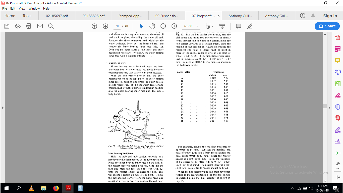
Without the proper Jaguar collar, the initial fitting of the inside inner race requires the use of a ‘temporary’ shim of known thickness, 0,100", between the hydraulic press piston (or whatever). The shim abutting the end of the hub, but inside the inner race - with pressure applied.
Lifting the whole hub carrier, the play can be read with a dial gauge. The difference between the play read with the temporary shim in place and the desired play is added to the thickness of the temporary shim to give the correct shim thickness. The temporary shim is then removed, and the correct shim fitted - and the inner race, still well greased, pressed in…
This may seem confusing - just remember that the inner end of the hub is the reference point. This is where the shim is fitted; to limit the travel of the hydraulic piston travel as the inner race is pressed ‘home’…
Again, all this is done with the hub carrier on the bench - turned upside/down as access to the bearings require…
this is an IRS that I purchased from my panel beater. I saw the radius arms sticking up in the air like a dead horse. I asked Bob about it, He says Oh, yeah do you want it? Ummm YES!! he said $150.00(US) and it’s yours. Give me another $50.00 and I’ll throw in all of the bright work from the car it came out of; which is was a Series II XJ12. I asked about the rest of the car, he said a tree fell on it. Oops, distracted.
I reviewed the link provided, and that seams a biit over kill why two grease fittings? or is the old one capped off and the new is, well, there on the other side. The Previous owner Drilled out and screwed in a grease fitting right in the top of the OE one. Only on one side of course. I figured I’d do the same on the other side. No?
Spacers
There was only one. that I retrieved when I took it apart. it was mangled and paper thin.
Lube
As I mentioned earlier on on this thread, the grease was literally hard as a rock. All of the bearings and mating surfaces had signs of water ingress. The race of the inside bearing is literally shreded. It looks like a weld that had failed - once jagged but smoothed over by friction. I’ve seen this before on an old Chevy Pick up. but the bearing had literally welded itself to the race and the spindle. To the point where the wheel locked up. Of course while I’m writing this I’m thinking when I got the IRS it was locked up, but I thought it was the brakes. when I got it part and saw how hard the grease was, I thought that was the issue because a bit of brakekleen freed it up so it would spin by hand… Doesn’t matter cause the bearings are already in the wheelie bin.
So you rely soley on filling up that immense cavern with grease and relying heat to get grease, probably not grease by then, to lubrication to the wheels bearings?
when I did the front bearings, I did the traditional hand job packing the bearings and didn’t fill the huge cavern with grease. I probably should revisit that?
I literally giggled when I read that. Fortunately I don’t have knock offs, so a bit more effort will be required. I have to say I am disappointed cause I was really hoping to have this in the car by now, and all I’d be doing is cleaning up the rest of the car to Drive to California for the big 50th Anniversary of the XJ. I wanted to take the pink Series I but there is no way. too much work and not enough time. I’m gonna leave out the financial side of it.
Thank you so much for the detailed assembly steps. And once again a sincere thank you for your help.
Mark
Hand packing the front bearings is what I do too, then a bit into the zerk once it’s buttoned back up. If you fill the cavity then the grease will ultimately expand and force it’s way past the seals. Just put a gun on the zerk and give it a couple of pumps.
Actually, I’d rather have a wheel come right off than have it part at the halfshaft, flip out, and form a very large parking brake.
Don’t rush. the drive to California would have been nice, but don’t start off on a long forced march until you’ve shaken the car down well enough to chase all the loose ends. A drive to the Dollar Store to get pencils can also put a smile on your face.
I have just finished removing all the grease from the front hubs of my ‘S’ the previous PO literally filled the entire inner area of the hub, it took ages to remove
The PO did the same thing with this IRS. after nearly 50 years of sitting? I don’t really know, but the grease is hard as rock. WD40 or BrakeKleen & a plastic trim tool and chipped a way at it it did come off in chumps which was nice.
the camber seemed to hold it on when this happened on mine and another gents V12 manuals
do you Andrew remember in the early J-L days, an engineer fellow, Jan Wikstrom described machining a groove on the shaft where the thread meets, to correct a design fault ?
I certainly didnt giggle when I saw what was rattling around in my hubcap (on the freeway)
Now I know why they call it the “Jesus” nut
(the shaft snaps where the thread ends, meaning no top link to hold the wheel on)
When I jacked the car up, I was able to flop the wheel down with no tools, just pivoting on the lower arm.
I strongly suspect this is why Jaguar took to using loctite on the shaft to hub
Frank
Are you sure the XJ6 end float is 0.002-0.006".
I’ve just been thru this on my 85 XJS and went with 0.002" from a tolerance listed as 0.001-0.003".
And even cold I am a bit annoyed with the movement in the wheel…but I have not checked it “hot” yet…so hopefully the clearance is for the difference in expansion between the steel shaft and the aluminium housing…and when warmed up it will be firmer…
Regards
Matt
Yep…The radius in the transition is mentioned in Kirby’s book. It’s a little on the “sharp” side. I posted a photo when I had mine modified to show what is possible there…but I should have taken a before and after shot. It is a classic method of reducing stress at these types of transitions…with a gentle transition in the form of a generous radius between the threaded portion and the main shaft…even a little bit of undercut is preferable to a sharp radius.
Two specs was found at different places. Indeed, 0,001 - 0,003" as you refer to seems more prevalent. So I think you are right, and I stand corrected - indeed, elsewhere adjustment is deemed necessary if the lash is 0,005" or higher.
You can of course re-check the lash in-car any time, but if you set lash correctly the movement of the wheel is as it should be - for whatever reason. To tight and the bearings will quickly overheat - to loose and you may just have a lively rear end…
This is also mention in the XJ-S book.I know I’d pay attention to the fact the washer was butted right up to the end of the threads on the shaft. Worse case, I’d stick a thicker or another washer on it so the clamping force is spread out over the threads rather than butted right up to the end. Idk, unless I’m missing something, I’d think that isn’t so much a design flaw as an flaw between the wrench and the hub.
I thought you were being candid… I didn’t release that is something that really happens. I don’t think I’d be giggling either… That would make for a very unpleasant day.
I was a kid, I’d put rocks in the neighbors hubcaps. They’d pull out of the driveway, stop, get out, look around the car, get in drive a bit farther then stop, look, get back in… and repeat… Turn around go home, take the caps off and empty the rocks out. I also did it to all of the faculty’s cars (that had hubcaps and yes I had help) on the last day of school. I was in 8th grade. It was pretty funny until the cops showed up - Then it got kinda real…
Setting the hub preload
I’ve been thinking about this a lot today. Ive decided to build one side at a time.
I’ve been trying to wrap my head around how to get the preload measurements when the bearings are pressed on the hub. I can’t imagine that the inner bearing has to go on and off the shaft a couple of times. Once to get the measurements based off the “big” shim. Then press it off again, and install the proper shim, then press it back on again. and pray that I can do math properly. Cause if I screw up, then it has to come apart again, and run the risk of damaging the water slinger and seals…
I’ve got to be missing something.
I’ve looked over the Series 1, 2, and 3 service publications on the IRS - rear hub and carrier assembly. If I understand the manual correctly, the bearings should’ve stayed in the carrier and not stuck on the hub when it was removed from the carrier - Like when I did it.
When it came a part, it came apart with a vengeance. Big Bang! all of the spacers and props few everywhere. The hub and carrier were the only two bits left on the 20 ton press. I’m pretty sure it took nearly all of the 20 tons too. when I saw the state of the hub, spun bearing, I figured that is why it took so much force. it was essentially welded to the hub shaft. Maybe this isn’t the case?
When I went to retrieve the hub and carrier, the inner bearing, Grease seal and spacer were resting in the carrier - not in the race or fitted where the parts are supposed to be but just hanging out in the recess of the carrier.
when I gathered up the hub, it was loosely fitted in the carrier I just pulled it out through the front of the carrier along with the outer bearing, grease seal and water ring; which are still stuck on the hub.
Is that how this was supposed to come apart?
The pictures show the hub being pulled off with the carrier still attached to the fulcrum. When I tried that the it just pushed the half shaft inside the hub. Or is the photo of the hub being removed on a knock off configuration?
I’m thinking about making this. but I’m not sure what the dimensions are. Does anybody know?
The 50th Birthday of the XJ
I’ve pretty much given up on driving a one of the Series III’s down to the festival. The pink Series I would never make the 2200 mile trip either would the SWB Series II. So I’ll be taking my time on this IRS Build.
if you need parts, you’re welcome to any of these. just pay shipping and make a donation to the board. these are from my S1, well all except for the finned cover
Thank you! I will let you know when I get that far. I would like to replace the scored hub. I don’t see that in the box unless it’s under the cover. Too bad on the finned cover. That’s really cool and would look really awesome on my Power lock. Hehe… Thank you again for your more than generous offer.
It’s a fatigue issue. When a shaft is subject to lots of cycles…say…100’s of thousands to many millions…then the radius in a transition between shaft sizes is very important to the life of the shaft. It’s in all the textbooks and has to be considered in the shaft life calculations. The washer is there to spread the load on the face of the hub and there is clearance required to develop the contact pressure so everything is held in a tight sandwich and the inbuilt clearance can take up the difference in expansion between the aluminium and steel shaft. A complicated arrangement …all the manuals would have benefitted from a decent sectioned view of the assembly so any maintainers could understand how it goes together. The description in the manuals I have are not enough to understand how it goes together.
thats where the dummy bearings I mentioned earlier come in handy…otherwise you do need to press on & off.
here is another thing that would be handy to know…if one test endplay before dismantle, like it shows here to test after then, unless the bearings or other parts are worn, it should all go back together, as it was set up in the factory, with the original spacer
finally, I found it confusing that endplay is quoted, not pre-load, as tapered roller bearings are normally pre-loaded. I set mine up as per manual with endfloat.
in my opinion, if this is done wrong, too much preload would stress the shaft, and contribute to it breaking.
I do not fully understand what is going on here, have asked about this before, and received different answers
the diff output half shafts are also quoted as endfloat setup
the fulcrum bearings are setup with preload, so its not as though Jaguar stated the wrong thing, one would think
Heat. The ally hub carrier will expand when running and take up the end float. At least that is what my thinking would be. The fulcrum bearings are under a lot less rotational force so can withstand the preload. However due to the limited rotation that they are doing I will probably set mine up with minimum preload when I get around to replacing the ones on my ‘S’