Hello,
I would like to share my journey as I re-assemble the 1970 E-Type FHC from a bare body shell. I hope some of the challenges I ran into with parts and fitment will help others. I am not a professional mechanic but I feel I am mechanically inclined and somewhat experienced and proficient.
Front frames:
When assembling the front frames, I found that starting at the torsion bar reaction plate bolts first worked for me. I first loosely installed the frame bolts to the body and 4 frame pieces. After fighting the line up of the reaction plate bolts, I removed the other bolts, fit the bolts in the reaction plate, and then I could line up the other bolts to the firewall and frame members. The frames away from the reaction plate had more “flexibility?” to line up the bolt holes with a few alignment drifts.
Lower wishbones:
It was very difficult to remove the torsion bars when I disassembled the car 2 years ago. Very difficult. I discovered why. The right hand lower wishbone front lever was the left hand part. That angled the torsion bar at the wrong angle (towards the outside of the car rather than towards the reaction plate bracket.) I purchased a complete RH wishbone. With that I found several quality control challenges. The fulcrum shaft was assembled with the longer end towards the front rather than to the rear of the car. This causes a misalignment of the cotter pin holes with the castle nuts when the bushings are installed. The threads on both ends of the fulcrum shaft were damaged. I repaired them with a thread file then a thread chaser to allow the nuts to turn on. The splines on my original stock torsion bar would not go into the splined hole on the lower wishbone lever. It appears to me the plating process reduced the clearance to an “interference” fit. It would be impossible to assemble the torsion bar to the lever on the car. It would not even begin to engage the splines. Using a triangular file, I removed the plating until the torsion bar engaged the splines with a feel as it had with the original lower wishbone lever. The mounting hole for the sway bar link bolt was also an interference fit and had to be clearanced.
Torsion bars:
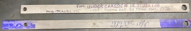
I found I had to install the torsion bar in the reaction plate bracket before fitting the lower wishbone to the frames. I am now proficient at installing lower wishbones. It’s only time. I drilled a piece of 1/4" thick by 1" aluminum flat bar on 17 3/4" centers per the factory shop manual. The spec for chassis #'s under 1E.35382 LHD is 17 13/16". AFAIK. My understanding is Jaguar installed a stiffer torsion bar in the chassis after that. I attached the tool between the picture frame and lower wishbone shock absorber mounts. I applied a piece of painters tape around the torsion bar at the front end and marked it at 5 points around the bar to keep track of its position as I rotated it. I presented it to the front wishbone lever one tooth at a time. I went around a full revolution to establish the feel. At one point, I found 2 adjacent teeth that felt about the same beginning of engagement. I picked one and the bar pushed in almost half way. I used a small air hammer to seat the bar. The rear of the bar is flush with the rear of the bracket and the locating bolt for the torsion bar in the front wishbone lever fit right in.
Upper wishbones:
I purchased two upgraded upper wishbones a few years ago. These are assembled with the upper ball joint in place. I purchased the upgraded adjustable fulcrum shafts. The fulcrum shafts were not drilled for the split pins (cotter keys) used to retain the slotted nuts (castle nuts.) I determined the distance for proper location of the 1/8th" holes in the threaded end of the shafts using the original shafts as a guide. It had to be fairly centered as alignment with the slots on the nut was critical. Now that was interesting as on the 4th hole, I managed to break the tip off of my pilot drill. It stayed in the hole. I dealt with that for over an hour. Tried to drill at 90 degrees but the drill tip was in the way. Finally, when it figured out I was not going to give up, the tip allowed me to back it out with a small pick and I completed the hole.
I installed the upper wishbone in the frame.
Stub axle carrier:
I used bungees to support the stub axle carrier as I installed it in the lower ball joint. Not wanting to stress the joint at the limit of its travel. I tied the frame to the axle of my floor jack. I raised the lower wishbone enough to first install the shock absorber, then engage the upper ball joint. After tightening (lower ball joint to 75 ft lbs and upper joint to 60 ft lbs I lowered the jack. The upper joint gaiter split. I found it the be very stiff, almost brittle. Luckily, I had 2 new gaiters in my spare parts from a ball joint rebuild kit. So, that is buttoned up.
Sway bar:
Fairly straight forward. The lower link bolt is slightly longer than the link to sway bar bolt. The lower lever is a bit thicker and the nyloc nut needs to fully engage the threads. I found I needed to orient the links to fit. They are new and not really square(?). Anyway, after some fiddling, they fit with no resistance.
It is now beer:30 and I am off.
I hope this information is helpful. I will continue sharing as I progress if this is the correct venue.
Cheers,
Mike