Rebuilding the IRS Hubs - Part 2

Back to the project after interruptions by Ian the Hurricane. No problem here, but my son’s family is in Tampa and he is in Nebraska working. All’s well that ends well.

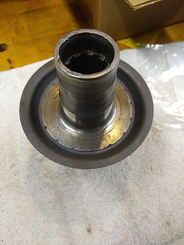
I am working the hubs and specifically the Outer Fulcrum Shaft and setting the new bearing pre-load. I am using the instructions from the shop manual. see pic.

And to make sure I’m doing it correctly, I’ll ask. As I understand it, I have disassembled the shaft and replaced the bearings. I counted the shims between the spacer tubes: 4 Xs 0.007" = 0.028". I added another shim of 0.005" to be too loose (pre-load wise) and put it all together. I did not fabricate the 3/8" steel plate with a tapped hole to screw the Fulcrum Shaft into, rather I simply screwed on the nut and held that in the vice. Then I fitted the assembly without the seals. So, Seal Track tp Seal Track. Big flat washer against the Seal Track on the other end and a number of additional washer to get to the threads and the nut. Then I tightened the nut to 55 lb-ft. Rotated the Hub a bit and pushed towards the vice. Took a measurement between the Big Flat Washer and the Hub’s machined surface. Then I pulled on the hub and took another measurement. What I’m looking for is the difference between the push and pull measurements.
Is that correct? Should be 0.000" to 0.002".

Hi Scott…you added more shims to make it a bit extra loose…you then measure the gap you have and take out shims of that amount…that gives you 0 endfloat…deduct more to give you preload…Steve

Right Steve, but it’s the gap created by first pushing the hub and then pulling the hub?

Hi Scott…when set correctly there should be no push/pull…youve started with more shinm so you get push/pull…this tels you how much end float you have…then you can calculate how much shim to take out to give desired pre load…hope this makes sense…Steve

Okay, I got it. When I first took it apart, there were four 0.007" shims between the two Spacer Tubes. But there was also two smaller - as in less diameter - shims that were also between a Spacer Tube and the bearing that were 0.004" thick. One of these was mangled.


I reasoned these 0.004 " shims were centering shims intended to be used between the Hub and the Wishbone; somehow they got into the Fulcrum Shaft space…I’ve no idea how.

So my initial attempt to measure the end float was to discard those small shims, add a 0.005" shim of the normal size to the four 0.007" shims thereby yielding 0.033" of shims between the Spacers. When I put this together and torqued it to 55 lb-ft, I measured a gap of 0.018" between my Big Flat Washer and the machined surface of the hub. I thought that was the gap I was trying to find. But it is not. I should have pushed the Hub towards the vice and then pulled the Hub away from the vice and measured that difference. Let’s say that was 0.012" (I will do that this morning). I then would remove one 0.007" shim and one 0.005" shim to yield 0.000".
Pictures coming in a minute…I need to upload them from my camera.

Hi Scott…those small diameter shims are typical of what iv found previously…in practice the outside diameter isnt critical…also i dont see why the shims are in between the 2 tubes…later xj6 cars had a one piece tube and the shims fitted at one end…the reason shims get mangled is when you slide the shaft in/out when fitting it in the wishbone…so take care there…Steve

I appreciate your help Steve. It wouldn’t matter where the shims were located as long as they fit somewhere between the Spacer(s) and the bearings. On the Series 1 car like mine, they used two Spacer Tubes. The larger outer diameter shims are what was in between the two Spacers and they match in diameter to what I purchased. The smaller ones are more fragile. That one mangled shim was sticking out of the Spacer Tube on the right…more in the Spacer than out of the Spacer.


The wood brace is simply there to keep the hub from moving when I torque the nut.

Hello Scot,
Where did you get the information from, that you should be aiming for Zero End Float only and not Pre-load? The tolerance is 0.002" (0.000" to -0.002") and although 0.000" is within the specified tolerance range, aiming for the low end is a mistake, in my opinion; as it won’t stay at 0.000 for long. Normally, when either making or adjusting something, where a tolerance range is specified, you would aim for mid tolerance; as it give the best chance of being in tolerance. Taper Roller bearing prefer to be in pre-load than end float at the best of times. The arrangement of theses bearings yields very little rotational movement, with pre-load being far more desirable. Therefore, aiming for the upper amount, in terms of pre-load, is a better strategy.

Regards,

Bill

Hi Bill. I corrected my initial statement to reflect 0.000" – 0.002". Perhaps I have a misunderstanding in how the tolerance is written? I take the Repair Manual statement to be from 0.000" to +0.002". I.e., that dash between the numbers means “between”. I do not take that as a minus sign; i.e., not to mean 0.000" to -0.002". Am I misinterpreting this?

I do understand tapered bearings function best with a pre-load vs. some End Float. But, that isn’t how Jaguar specified it in the early 1960s I don’t believe. Probably I am wrong. Nonetheless, nowadays we set a pre-load on tapered roller bearings. What I intended to do - once I figured out the procedure - was to find 0.000" of end float and then remove another few thousandths to establish some preload.

I do not know how to verify pre-load in this setup.

Edit: Oh yes, I am setting this pre-load with minimum grease in the bearings and none inside the Hub housing. I plan to first set the pre-load and then to grease the system using the shims I determined. Is this proper?

Hi Scot,
To your comment above: no. Pre-load has always been specified for these bearings.

I wrote the tolerance range as 0.000" to -0.002", simply as an abbreviation to using the word pre-load. In all of the Jaguar Manuals I have, covering from early S1 cars to the last of the S3’s, the fit of these bearings have been specifically described as being in pre-load. From the S1 book it states “the correct bearing preload is 0.000” to 0.002" (0.000 to 0.05 mm)"

You do so in the manner that you’re currently going about it.:

  1. Use a stack of shims that will give measurable End Float
  2. Measure the End Float and add 0.002" to the resulting measurement.
  3. Remove shims equal to the value calculated in point 2.

The result will only be as good as the accuracy of the result obtained in point 2. You need to take care that the respective bearings are correctly seated when taking the measurements, pushed away and pulled towards you. This can be a bit awkward when manipulating the Hub Carrier and using the feller gauge. Accordingly, I have a steel plate setup, as described in the workshop manuals, to which I attach a dial indicator via a magnetic base. The correct End Float is the maximum value I can measure, when ensuring that the bearings are seated correctly for both direction readings.

Regards,

Bill

2 Likes

Thank you Bill. What you state in 1,2, 3 makes more sense to me than what I was reading in the manual. I noted it states pre-load, but then I read what I took to be End Float numbers. You of course, have interpreted it correctly. I was thinking 0.000" to 0.002" of end float whereas you’re thinking pre-load. My bad and my misunderstanding of what the manual meant.

I can do the measurement with a dial gauge; that will be easier. Thanks for straightening me out.

It was a fun day setting the Pre-Load for the Outer Fulcrum Shaft. Thanks to Bill and Steve for setting me straight on the procedure. I was struggling with the concept of setting bearing pre-load using fractions of an inch vs. lb-in of torque as the setting value. My head kept wanting to call it -0.002" (negative) end-float as opposed to 0.002" pre-load.

Using my setup with one nut on the Fulcrum Shaft held in the vice, and noting that when I disassembled the Fulcrum Shaft there were four 0.007" shims in between the two Space Tubes. I added an additional 3 Xs 0.004" shims thereby creating a total 0.040" of shims. I assembled this like in the picture above and rotated and PUSHED the Hub towards the vice, got a measurement (0.025") and then PULLED the Hub away from the vice and got a measurement (0.022"). (I used a feeler gauge rather than a dial indicator…it just seemed easy enough.) The difference was 0.003". Removing a shim equal to 0.003" would yield zero Pre-Load, but we want 0.002" of Pre-Load, so removing a shim equivalent to 0.005" would yield that. I didn’t have a 0.005" shim in the stack, so I removed one of the 0.004" shims to yield a Pre-Load of 0.001". That’s acceptable.
That went quite smoothly and I was ready to fit the seals. But then I discovered I could not remove the only nut I hadn’t taken off previously. It was apparent the end of the Fulcrum Shaft had been abused with a hammer - likely the cause of the damaged centering shims I found. I eventually removed the shaft again and used a 1/2" air impact gun to finally get it off. I’ll order a new one but to finish this right side Outer Fulcrum Shaft, I took the shaft from the left side Hub.

2 Likes

I find it helpful to use only a very light smear of grease on tapered bearings when checking end float or preload to avoid any ‘stickiness’ when using a dial indicator. Then once the shim stack is defined, I apply my usual amount of grease before final assembly.

1 Like

Looking at this hub it has a lot of damage on the end where the spacer to set the bearing endfloat sits.

You probably ought to address this.

1031de0cb7c7fc82c7d45234b3f98dbd9f7e1281_2_375x500

That’s what I did Steve. Smeared a bit of grease on the cups and the rollers and then wiped it mostly off leaving a thin film.
Andrew, good observation. This is the Left Hub that had the damaged U-Joint and the “bruised” area in the metal surrounding the Inner Seal. I suspect the U-Joint had been changed in situ and the job was botched. I did take a flat circular fine grindstone to it but frankly, it needed a lot more than that.

I don’t have a lathe or I might have done more. I came to the conclusion that it really didn’t matter as it abuts the Spacer and I just strived to eliminate any protuberances and accepted indentations relative to the Spacer. I.e., as long as I get the Spacer sized right, the Pre-Load will be correct. Perhaps I need to do more? What would you suggest?

On the Outer Fulcrum Shaft for the right side, I used a dial indicator to set the Pre-Load as the machined surface to take the measurement from was rough


Unfortunately for me the supplier for a replacement Fulcrum Shaft is out of stock for two more weeks.
Therefore I “fixed” the threads on the Fulcrum Shaft I have and used that to set the Fulcrum Shaft Pre-Load. In this case there was 0.002" of play. To that I added 0.002" and needed to remove 0.004" from the stack up of shims. Conveniently, I had a 0.004" shim and I removed it.

As Bill A. had recommended it was a lot easier to use a dial indicator vs. feeler gauges. I should have done that with the first hub as well.

Hello Scot,
The problem with the irregular surface on the end of the splined hub, is that the high points will be spreading the load applied by the nut, over a smaller surface area. Depending on how diminished this surface area is, there could be a strong possibility of the high points imbedding in the surface of the spacer over time, resulting in increased pre-load. This in itself may not be an issue, but I rather make an assembly that I’m confident isn’t going to change prematurely.

Setting the Hub up in a lathe and taking the minimal amount of material off to achieve a true, full face, is the most convenient method. In the absence of a lathe, I would do as follows:

  1. assemble the Seal Track on the male splined shaft
  2. smear a small coating of Bearing Blue on the face of the Seal Track
  3. assemble the Hub on the splined shaft and tap it lightly against the face of the Seal Track to transfer Bearing Blue to the high points on the face of the Hub.
  4. remove the Hub from the splined shaft and carefully relieve the high points with a fine file, or scraper.
  5. repeat steps 2 to 4 until a good contact area between the end surface of the Hub and the face of the Seal Track is achieved.

Regards,

Bill

4 Likes

Okay. Good idea and thanks. I can do that. I’ve about worn out my welcome with my lathe owning friends.
But, we have a jury rig system where a drill press is used to hold the part. Then a spinning hand drill is used to polish or make round the part in the drill press. For some unknown reason this is locally referred to as a German Lathe. I was thinking perhaps I could mount the hub on the drill press table and then fit a sanding disc to the chuck of the drill press. I break out in a sweat worrying about securing the hub, making the table square and keeping the hub vertical. Your idea is slow but sure and safer. What say ye?

Hello Scot,
By the time you sweep the table of the drill with a dial indicator and confirm, or make the table true with the spindle, I suspect that the end of the Hub could have been cleaned up quicker via the method I’ve described. I used to do a lot of machine tool reconditioning, where a lot of hand scraping was done to bring elements of the machine back into squareness or alignment. The surface area of some of the surfaces scraped, measured in the square metres, so the size of the Hub end is infinitesimal.

Have you examined the spines of this Hub that engage with the wheel? If these aren’t in good order, you may be whipping a dead horse and the Hub should have been replaced in the first instance.

Regards,

Bill

Damage here is common when removing the hub. I have made a mandrel that fits there and protects the hub from the hammer.

If they are like this I skim them flat in the lathe. I think you need it to be flat as the 120lbft you tighten it to is potentially going to distort the spacer and mess up your endfloat.

Edit. I have just read Bill’s reply. That looks like a good (and easy) solution. If you don’t have proper blue you can at a pinch use a Sharpie marker. That’s what I used when I needed to flatten the gibs on my cheap and cheerful Chinese mill.

No…I can’t take anymore! I’m not a machinist, I’m a Mechanical Engineer. I’m retired. I’m 75 years old, and more of a woodworker and probably a 2nd rate woodworker even at that! So, here is my take on all this.

I took the Hub, not the Hub Carrier, to my local machinist. He does mostly engine rebuilds and stays within his sphere of knowledge. Wes looked at the mating surface of the hub-to-spacer for me and said there are no raised areas but many “cavities” and he’d probably leave it alone. We chatted for a bit and I explained my idea of the drill press; here is what I’ve done.

Did I map the surface of my wood-working drill press’s wooden table? No. I did find a very straight rod and put that in the chuck and used my carpenters triangle to verify it was vertical to the table in multiple directions. It was…pretty much. I had a number of cut-off wheels and I mounted them into the drill’s chuck until I found one that was straight and didn’t wobble to the eye. Pic three. Then I marked it with machinist dye - okay, I used a Sharpie…thank you Andrew. That’s pic four.


r


I adjusted my drill press to run at 200 rpm and brought the cut-off wheel in contact with the spindle end. Barely touched it and inspected the ink. Hmmm…pretty good, So I turned the Hub 90 deg and touched it again. Still good. Another 90 deg and good and the last 90 deg and I’m liking this.

So back to the drill press and more grinding and rotating. I think it came out pretty good.

It is very difficult to get the lighting right on these pics. The dye reflects and sometimes looks like it is there when it is not. So, looking at it in person, I achieved a solid ring of contact showing around the entire spindle end. Sometimes wide, sometimes thin, but a consistent 360 deg of shiny surface all around. The point is there are no high spots. At least, that is what I think the pint is. Ooops! Freudian slip! Here’s more pics.


Shoot me, not you Bill you’re too good of a shot!. Andrew, please don’t tell me you’re a small cal Champ too! :slight_smile:

So back to the beginning of my answer:

The answer is, “sort of.” I obtained a used splined hub and discarded my original splined hub. The replacement is much tighter in the hub than the original. So, I’m saying the hubs and the splined shafts are in serviceable condition. And I’ll drink to that!

1 Like