Sometime I’m planning to swap my JH gearbox for one I’ve had rebuilt, which is only about 50 numbers later than the original. The original one is very noisy on the bearings, which quietens down a bit with the clutch pedal depressed. I know it’s possible to do without removing the engine as well. Transmission tunnel off, floorboards out, etc. I’ve had all that out quite recently when I fitted a new floor. I’ve read the procedure in the Service Manual, so basically know what to do.
My query is: are there any particular tricks I should know about? I’m thiking particularly about the clutch shaft, as I’ve never removed one before. Are there parts on it I should consider renewing as a matter of course while things are apart?
Any hints gratefully received.
Chris
Regarding hints, don’t!
I have or more accurately my mechanic has done clutch only on 120fhc for me not taken motor out but thought it was a rough way of doing it and not really recommended could be totally wrong.
Will be very interested in other comments and how you go
Regards terry
I have removed my 140 trans separately and attached to the engine. I found that pulling the engine and trans together is the best and fastest way to go. No heavy lifting and alignment is much easier and accurate.
Hi Chris:
Biggest hassle I had with the clutch pivot shaft removal was the split pin that keeps the spring compressed. Needless to say, it had never been off since the car was manufactured and this meant cutting the ends off with a hacksaw and then filing down the nubs in order to pull the shaft out through the frame and remove the spring and washers off the end that comes out of the bell housing. I had thought of removing the clutch pedal off the shaft, however, after almost sixty years there was no way that was coming off until it was clamped in the vise on the bench and some heavy persuasion was applied. I don’t have a hoist and working with the car up on stands was, to put it mildly, a sod of a job. Of course, I should have done this when I had the gearbox out earlier in the year as it would have been a bit more accessible, but we all know about hindsight… By the way, I removed my gearbox, after supporting the rear of the engine, up through the cockpit (DHC, making it a bit easier). Biggest problem for me was separating the two, many hours (literally) of gentle prying with various implements ranging from initially long screwdrivers moving up to pry bars from the top and then the bottom and so on. I would add that doing this single-handedly in my 78th year was, shall we say, taxing. In retrospect it might, as Terry suggests, have been easier pulling both engine and gearbox as one unit! One thing you’ll want to do is check/replace the bushings on the ends of the pivot shaft (that holds the throw-out bearing) and check that the small holes designed for lubricating them are clear (mine were totally clogged with accumulated dirt). In addition, I replaced the bushings on each end of the pivot shaft as well as the shaft itself. My original shaft had gotten scored, probably because the bushings had never been lubricated, a fault I am entirely to blame for as, until a good lister clued me in, I had no idea it had two holes for that very purpose! Good luck!
Chris.
Gearbox removal. I last removed mine with the engine in place ('120 OTS). Other than sore upper back muscles the next day, I remember it being as a non-event. I placed a rolling jack under the gearbox, raised it slightly and pulled straight back. Of course I had already moved the driveshaft out of the way and other ancillaries such as the speedo cable, reverse light wiring, clutch linkage, etc. Also, the back of the motor was well supported. The actual removal part took some ten minutes. I’ll agree with the others that it is heavy. At one point I had the assembly sitting in my lap while seated on one chassis rail and thinking, “Great, now I have to get up and manhandle it out without scratching anything before my legs go numb”. You’ll benefit with an assistant for that part.
Clutch shaft. I won’t address that part that the clutch pedal attaches to as others – especially Rob Reilly – have already covered it in detail. I will say do pay particular attention to the throw out bearing fork taper pin (very common for it to be sheared/ distorted in some way) and also the pin on the bell crank at the exterior of this shaft. Consider drilling through both sides of the bell crank (not leaving it with just the one hole) and running a pin all the way through for extra support. On the bell housing I fitted oilite bushings with a high iron content and tiny Gits oilers to keep the dirt out of the oil access holes. Having them on helps to serve as a visual reminder to be oiled on occasion when working underneath.
Hi Chris. …dont forget to fit a new spigot bearing in the end of the crank…Steve
I’ve done it both ways, and I suppose there are advantages and disadvantages to either way.
Coming out forward with the engine, you have to remove the bonnet, radiator, generator, carbs and heater hoses if you have them. Now you’ll be tempted to clean the engine, clean the engine bay, paint the chassis,…what we call shipwright’s disease.
Coming out from inside you have to support the rear of the engine under the sump with blocks, then remove starter, seats, carpets, floors, gearbox tunnel, driveshaft tunnel and driveshaft, or let it swing down if you have the shorter one with the JH trans. Then use your trolley jack to get the gearbox loose from the engine and move it back onto the chassis cross member.
If you disturb your clutch during the process you may want to invest in a clutch alignment tool, low cost plastic, I’ve used it 3 times.
Here is the clutch pedal linkage for LHD. RHD is similar in some respects and a mirror image in other respects.

Thanks for all the advice, chaps!
Maybe I’m being thick, but having never taken a clutch shaft apart, I’m having difficulty understanding quite how it all works… I suppose my question is: for simple removal of the gearbox/bellhousing, does the whole clutch pedal shaft have to be taken apart (assuming no wear in the spherical bearings is suspected)? Once the pedal itself is removed, and the clevis connecting the pedal shaft to the release bearing shaft disconnected, is it possible to pull the pedal shaft towards the chassis against the long spring pressure and tie it back out of the way, possibly removing the spherical bearing on the bellhousing as well?
I’m taking a guess here not being familiar with RHD 120, but I think you want to remove the pedal, then loosen the 44 bolt and 45 nut holding the pedal arm and slide it to the left, then the shaft 47 will pull out of the 68 bearing socket and out far enough that you can get the bell housing past it. You don’t have to pull it all the way through the chassis.
You also remove the 62 split cotter pin, 62 washer and 61 clevis pin so the 60 link will drop free of the 55 lever.
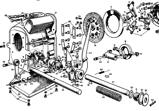
Viart has a mistake here on page 252. He shows the smaller o-ring inside the chassis. It is on the outside. There should be a flat washer inside there, so the end of the spring does not gouge into the chassis socket as it rotates.
Thanks, Rob, that’s what I was hoping to hear. I’m wondering if the pedal arm 43 even needs to be loosened and slid?
Assuming Viart’s drawing on page 252 is dimensionally accurate, which he usually is, I would say yes the 43 pedal arm is preventing the shaft from pulling out more than 1/2" so you need to loosen it and possibly the 55 clevis lever arm as well. There are Woodruff keys in them so be careful not to lose them. Best pull them out before they fall inside the chassis.
Chris,
The photograph on page 118 of Bob Exelby’s book might also help
Great tip! I looked it up and it has proven quite informative. I still haven’t seen a drawing of what goes on in the chassis rail (RHD). I assume there’s a welded-in cup of some sort to receive the spherical bearing… I note these have to be lapped in to their respective housings for a perfect fit. I’m thinking somehow rigging up the bush on a drill and using valve lapping compound might speed things up a bit.
Yes, there is a cup/socket welded into the outboard side of the chassis. There is an identical one on the other side for LHD cars if you want to look at it.
I can’t imagine needing to lap in the spherical bearing, unless it’s a badly made repro. Your old one is probably fine.
The only things inside the chassis are the end of the coil spring and a flat washer. The flat washer is to prevent the sharp end of the coil spring from digging into the inside surface of the bearing socket.
This is an image of a LHD but flipped or mirrored.

Thanks, Rob. Except, on RHD cars, the clutch pedal is on the shaft inboard of the chassis.
Rob,
This photo shows my rhd spherical brass bush, rubber seal and spring on the actuating shaft.

I think the rubber seal (not an o ring, more like a cup ) must go inside the chassis. I tried it on the outside ie between the spherical bush and the chassis and it didn’t sit right. I would assume the brass sits directly against the steel chassis.
But I can’t see that it (the seal ) would be much use on the inside - not much dirt is going to get into the bush from that side.
Here’s a picture of my rhd car. I think your picture may be a bit misleading in that I’m not sure they (rhd and lhd) are exactly mirrored.
Is the rubber pedal shown the accelerator? If so that would be proof.
Mine doesn’t have the washer/split pin to contain the spring, the clutch pedal does that job.
Always happy to be corrected.
Cheers
Garry
I think you are correct, Garry. The pedal visible in Rob’s reversed picture is the accelerator (adjacent to the bellhousing). It’s a bit of a brain-teaser, that picture!
The diagram from the spare parts manual shows a rubber gaiter apparently fitting over the bearing housing on the bellhousing. It doesn’t show one at the chassis end, just two O-rings of different sizes.
I still don’t know if the welded-in cup in the chassis rail is near the inner edge or the outer edge (or maybe right in the middle?). It seems to show that the convex bearing surface faces towards the centre of the car… I’m assuming the shaft is pulled though to the outside of the chassis when dismantling? Is the outside hole large enough to allow the large washer to pass through?
The cup is on the outer side of the chassis. And the brass bush fits nicely into it pointing towards the centre.
I removed the shaft to the outside. The large washer (close to 2 inch od ) is on the outside.
I’m now a little confused because I found the small washer much later, in the chassis. But the seal was with the shaft, therefore how could it belong inside the chassis?
This is incredibly timely, because just today I was preparing these bits for reassembly and I am fairly convinced that the seal should go inside the chassis. But why wasn’t it lying in the chassis with the washer. Yet another bloody mystery with this car!
I will check tomorrow whether the seal will come through the hole with the shaft and report back.
This is the photo I took when I pulled it apart. No small washer at this point.

I’m starting to get my head around it now! The large spring serves to pull the outer bush into its cup housing in the chassis. There must be some kind of washer between the spring and the chassis, as you wouldn’t want the spring to be butting up against the spherical bush itself. I assume the hole on the inner face of the chassis is smaller than the one on the outside. The inner end on the bellhousing seems straightforward to me. I still think there might be enough movement on the shaft before the spring is fully compressed to pull the inner end clear of the bellhousing and allow removal of gearbox/bellhousing…
Chris:
On a LHD car you can lever the clutch pedal away from the chassis by compressing the spring and wedge it (I used a block of wood) and this will allow enough clearance to withdraw the gearbox, I have done this two or three times over the years.
Chris.