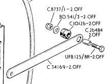
Better to stay with the original quality steel bolts. Galvanic reactions might occur.
Replacement bolts should be of like steel material . Grade 8 is overkill but will do the job! Stainless Steel may seem like a better choice but for this application stay away from them!!! Use standard steel.
Cheers,
Dick
1 Like
Hi Robbin/Dick,
Thanks for the comment. I’ll pick up steel grade 8 for that cut bolt. It’s a 2” so I’ll have to cut to the correct length.
These bolts are zinc plated for corrosion protection. Is this ok in your opinion for any galvanic reaction?
Michael,
You had commented on the ground kit and it’s potential misuse with aluminum radiators. The main use I think is to quash the potential static & other electrical voltages generated from isolated drivetrains or badly grounded subsystems going through the coolant to ground.
I think the key issue you raised is a good one: don’t use these straps to ground an aluminum radiator! The aluminum radiator was grounded. It should be isolated. I’ll look into how to do this with the bottom brackets. I’ll also have to make sure the fan shroud and cowling don’t short it.
Rubber grommets or bushings could work but I may need to modify or get new brackets.
The result was half the bottom radiator outlet was eroded along with much of the facing inlet of the thermostatic switch tee.
Except for one error with the S2, Jaguar mounted all E-Type radiators with electrically isolated mounts. This was true of the S3, which had rubber bushings on the stays and bottom mounts. IF this was compromised for your car, it’s worth correcting. No mods should be needed, just return to stock. The T-piece is also electrically isolated, as long as a two-connector switch was used.

Michael, on my S1, the radiator mounts onto rubber vibration dampers, through which, a metal sleeve and the stud pass. This would provide a ground path, so I’m confused with your comment about Jaguar isolating the radiator
I think you will find that there is rubber on both sides of the sleeve and washers. There is no ground connection through the rubber mounts.
I was thinking that the sleeve bottomed on the body, even though it is isolated on the circumference. Can’t remember now
Hi Michael,
Good info. Makes sense. I’ll ohm out the brackets & fan assembly to see what is the issue.
I have a new switch and it is the type that has one spade contact with the other contact being the switch case. The ground contact is then connected to one of the switch bolts with a spade contact/eyelet.
I know there are 2-isolated contact types (I installed one on an S2 I owned a few years back) but the S3 switches I can find are 1-contact type. Isolating this seems better to reduce the chance of electrolysis at the radiator outlet. Do you think this is important enough to try and find one? Do you know where I can get one?
Isolated switches were used from 1970 on. If you are using the older style switch, I’d also be cautious about the set point. I make my S2 radiators and S3 adapters to accept VW fan switches, rather than otters. The VW switches are isolated, and they are available with many set points.
If the 2-contact configuration is the right one, I wonder why parts companies ship 1-contact switch units as a Series 3 fan switch. I think SNG and Moss both ship 1-contact C45086 switches.
You mentioned set points. These switch have a set point that is not described. Do you know the standard set point? My thermostat is a 82c unit. Would a different set point work better?
The S3 fan switch is located in the BOTTOM of the system, not the top. So it’s reading water that’s just been cooled by passing through the radiator, 15 degrees cooler than the engine outlet. If you set up the system so that this cooled water is allowed to rise to 82, then the water exiting the engine will be around 97C. I send mine out with 75C/on, 70C/off fan switches, so at least the cooling system has a fighting chance of keeping things under control
Hi Michael,
I meant the thermostat (at the top), not thermostatic switch at the bottom. The top thermostat is an 82C unit. I was inquiring about the setpoint for the thermostatic switch.
Using your analysis, the bottom water when the thermostat kicks in would be 15 degrees (C?) cooler than that. Is that what the set point should be? Seems that there should be some margin so that the system does not oscillate but reaches a stable state?
As the temperature creeps up, at what point do you feel concerned? 85? 90? 100? The hysteresis of a typical fan switch is 5-10 degrees. If you have a setpoint of 75 fan on and 70 fan-off, then the fan will try to maintain exit water temperature between 85-90.
Just updating that the water pump is back in along with a new water heater pipe.
Will be flushing the engine with citric acid crystal to prep it for new hoses and radiator. Hopefully the engine will show itself to be free of the sludge seen at the thermostat switch tee area.
The car should be back together starting next weekend. Can’t wait…

Great news!! This issue has been put to bed…!
The work yielded the expected results. Just to close this issue and document what has been done for the benefit of others thinking of attempting to fix a similar issue, here is the summary of what has been done over the last 3 weeks. I’ll use the 9/10 list as a starting point:
====
Work done or to be done (as of 9/10)
- Remove thermostats & thermostat housing to radiator coolant hose/pipes - DONE
- Remove belts - DONE
- Remove fan assembly - DONE
- Remove radiator - DONE
- Remove header tank & associated hoses - DONE
Since 9/10:
6. Removed water pump & inspect: good. Cleaned water pump gasket area and remounted water pump. Engine cleanliness state also looked good. Seems that the sludge was amassing in the coldest area only. Used new elbow/heater, gasket and re-used the blanking plug.
7. Removed all hoses except for bottom left hose from radiator/Tee. Used this for the flush (clamp & unclamped).
8. Flushed heater valve & heater matrix. A little brownish water at first but flushed clean quickly. Note: This car had been flushed previously during the diagnosis so this is unsurprising.
9. Flushed heater metal line to engine bottom. Again a little brownish water at first coming out of the engine bottom.
10. Connected a clear tube from this line at the heater side to see water level during flushes.
11. Re-installed old hoses (after a detergent clean to to re-introduce junk in the engine) and clamped all lines except thermostat hoses. Unclamped some in order and used the thermostat hose to flush. Higher ports needed the radiator bottom hose clamped to get them to flush out.
12. Received HK009 hose kit & installed new hoses on engine except for the manifold hose segments & heater. Hoses connecting to the engine/radiator tee still not connected.
13. After this, clamped bottom hose and used 2/3 citric crystals per Michael’s suggestion first dissolved in 1-2 gallons of warm water. Fill half in each thermostat hoses & finish filling using clean water (I used hose water but added a dirt filter & cartridge filter to get as clean water as possible. Left solution in engine 2 hours.
14. Drain & flush 3-4 times to complete flush. Some brown residue but no particles were seen flushing out. A wet/dry vac & compressed air helped a lot to get most of the water out of the engine and pick up the mess.

- Connected the hoses for the heater matrix & valve. Engine now complete without the radiator hoses/components.
Radiator install & completion
16. Install thermostats and new housing with new hoses & pipes. Also changed the sender unit (not shown here)


-
Install radiator, belts
-
Install fan pack, header tank & associated hoses
-
Fill with water, run car & test for cooling - very good! between N-O even on highway. Before the car would have hit H. Filled using the Airlift - highly recommend although I found the unit works better with an actual vacuum pump as the compressor I was using could not keep up the flow and thus the vacuum developed by venturi stalled at about 18-20 in-Hg. With a vacuum pump, i was able to get 26-27 In-Hg.
-
Drain water & refill with 50/50 Zerex G05 per Michael’s suggestion. After some research myself, i am convinced this is a better coolant for these old cars. I also decided NOT to use the water wetter additive. The car runs cold enough and I did not get a clear answer from the question about if this additive will interact with the G05. After what I saw from what can happen with sludge, why chance it?
-
Did not use an in-line filter - not enough research yet on this and I did not install any of the RD grounding kit.


Had some coolant leak from the overflow when filling to the brim. No more after the coolant went down to about 1/2 of the header tank. I think that’s fine. Great news is all the hoses and gaskets (including the water pump install) is water-tight.
Car is now running well. From the diagnosis to full correction, it took 5-6 weeks. Replaced the hoses, tee, radiator, some pipes, parts and thermostat/sender unit.
Thanks to all here for your kind help and thoughtful suggestions. I really would have been stumped to do this rather involved work. Understanding how to flush and what coolant to use was particularly useful. This documentation is my way of “paying it forward”. Hopefully it will help others with similar issues.
My next project for this car is fixing the power brakes (the booster is still disconnected from vacuum), installing a 123Ignition (I just received the unit), and installing a more aggressive exhaust.
4 Likes
Good article: I completely trust M-B to have the correct engineering.
Great news you’re back in business!!! One item I would pay particular attention to in the future is the header tank developing pin holes. Those steel tanks are notorious for developing holes/leaks. Just keep it in mind.
Happy Trails,
Dick